Upper body support

a support and upper body technology, applied in the field of upper body support, can solve the problems of inconvenient wear, injury to the lower back, and considerable demands on the lower back, and achieve the effect of effectively shortening and effective lengthening

Inactive Publication Date: 2002-08-20
BENDEZY
View PDF5 Cites 61 Cited by
  • Summary
  • Abstract
  • Description
  • Claims
  • Application Information

AI Technical Summary

Benefits of technology

In a highly preferred form of the invention, the anchor plate is adapted to be attached to the extendible element of the lower portion of the dorsal member in two different orientations, such that in a first orientation the anchor plate extends outward from the lower terminus of the extendible element of the lower portion of the dorsal member thereby effectively lengthening such, and in a second orientation the anchor plate extends inward from the lower terminus of the extendible element of the lower portion of the dorsal member thereby effectively shortening such.

Problems solved by technology

Activities which involve either bending at the waist for long periods, or repetitive bending and straightening, such as various horticultural applications, impart considerable demands on the lower back and may cause injury thereto.
Further, during the use of such devices, the flexibly resilient element may shift from its most effective position, and may be uncomfortable to wear for extended periods.
Further still, such flexible material is of limited utility in spreading a load across the back of the wearer.
This construction limits the magnitude of the support able to be given to the wearer.
Other existing devices require a wearer to be attached to a fixed structure, and thus are of limited utility where the wearer must remain mobile, such as in many horticultural applications.

Method used


Image

  • Upper body support
  • Upper body support
  • Upper body support

Examples


Embodiment Construction

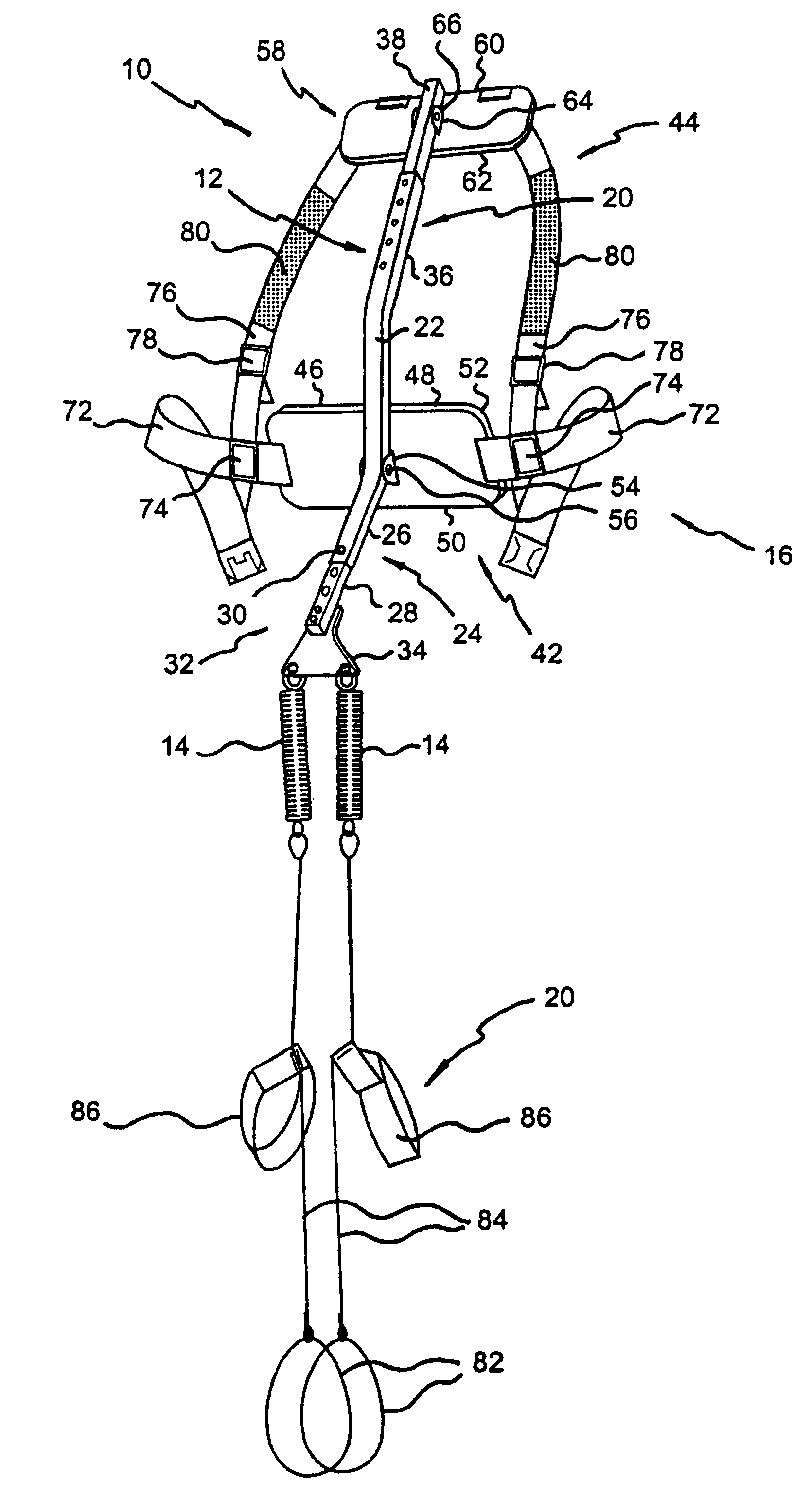
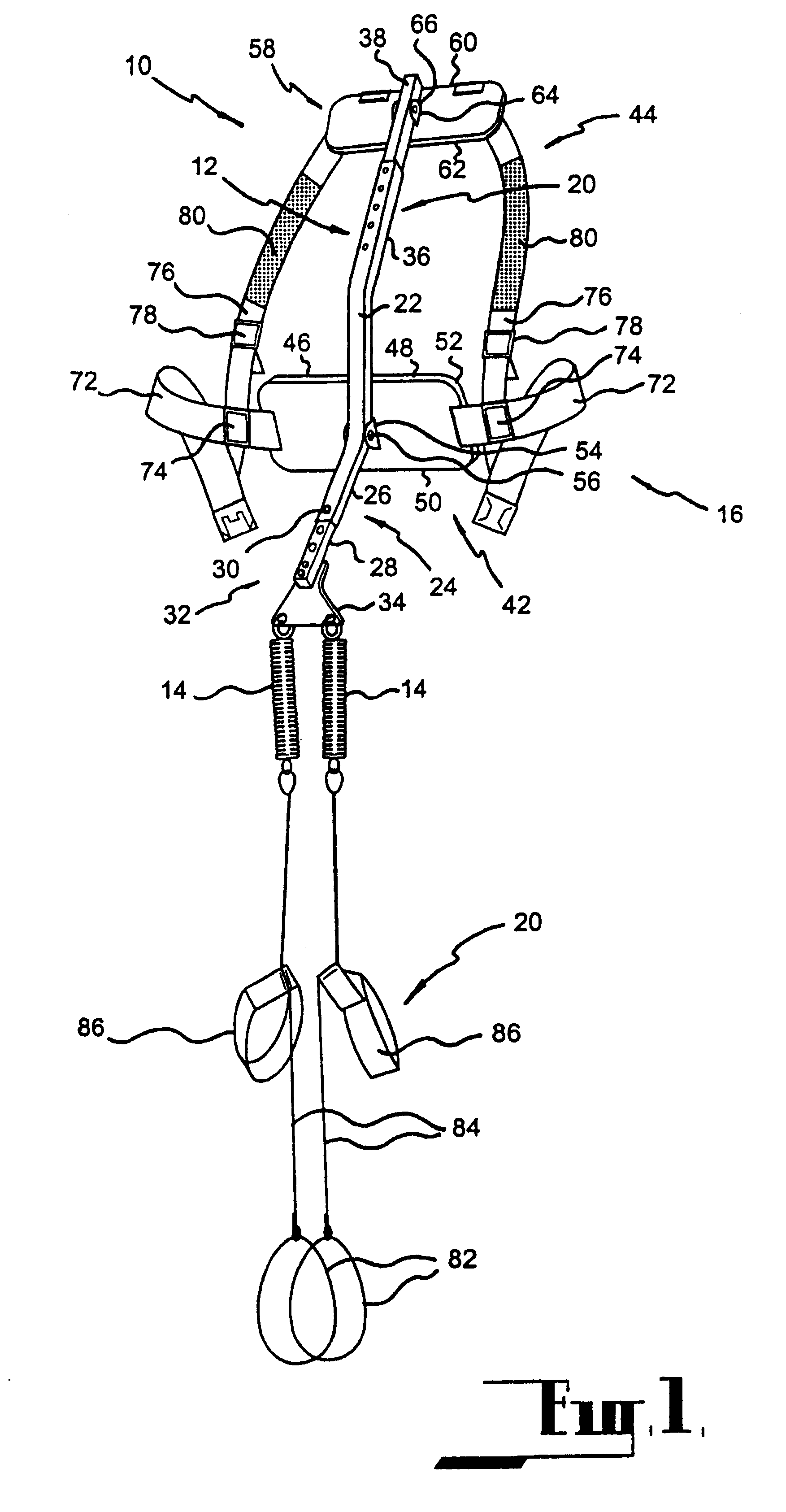
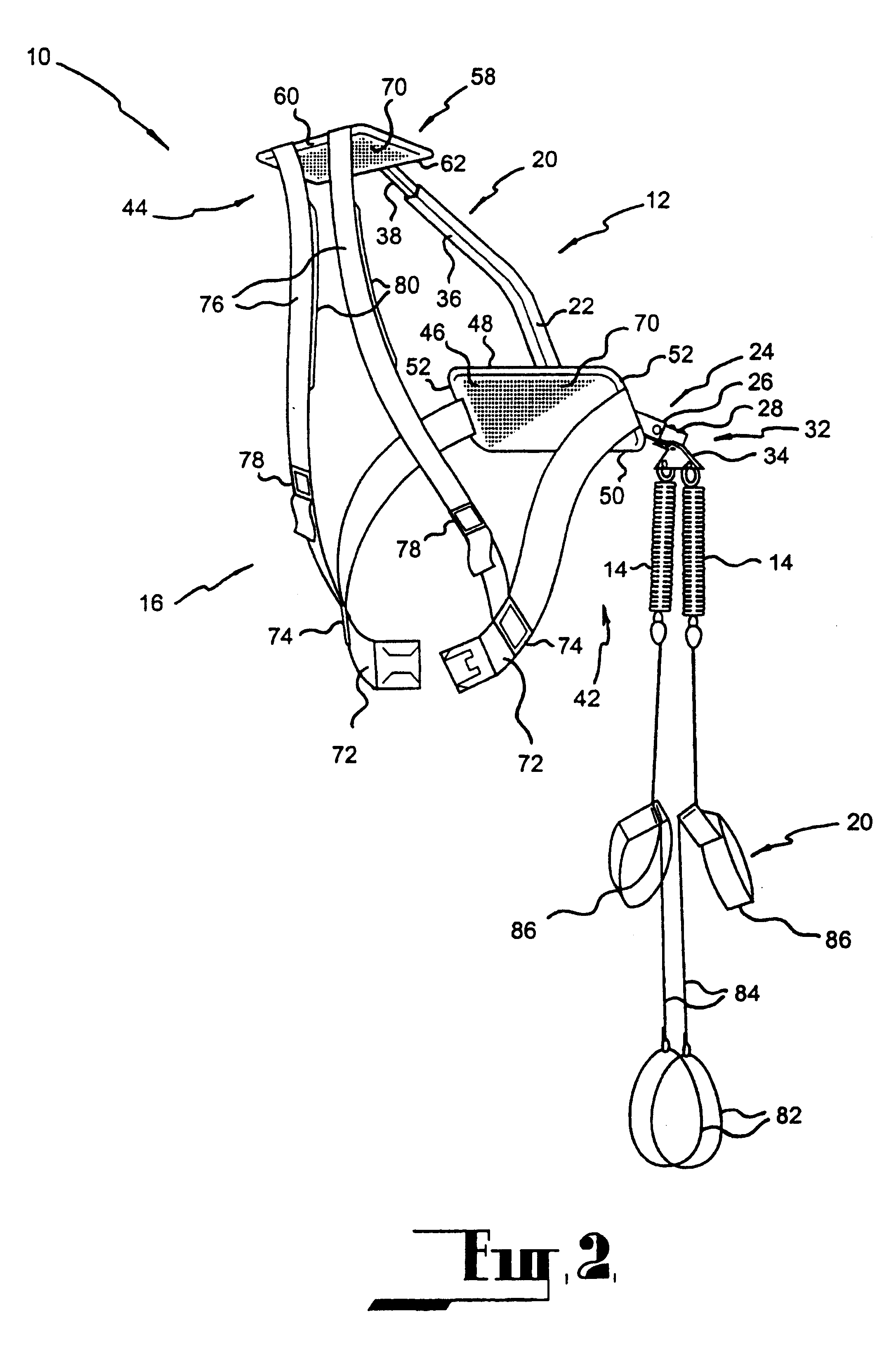
In FIGS. 1 to 5 there is shown an upper body support 10 in accordance with the present invention. The upper body support 10 comprises a dorsal member 12, two flexibly resilient elements in the form of springs 14 depending therefrom, a securing means 16, adapted to secure of the dorsal member 12 to the upper body of a wearer 18 and two leg assemblies 20, adapted to attach the springs 14 to the lower body of the wearer 18, as shown in FIGS. 1 and 2.

The dorsal member 12 is of a cranked configuration, comprising upper 20, intermediate 22, and lower 24 portions. The lower portion 24 extends substantially rearwardly of the wearer 18, as can best be seen in FIG. 3. The lower portion 24 in turn comprises a sleeve element 26, telescopingly received within which is an extendible element 28.

The lower portion 24 further comprises a means 30 for adjustably fixing the extendible element 28 in a particular position relative to the sleeve element 26. Releasably provided about a terminus 32 of the l...


PUM


Abstract

In accordance with the present invention there is provided an upper body support characterized by a dorsal member, having a lower portion which extends substantially rearwardly of a wearer, and at least one flexibly resilient element operatively interconnected with the lower portion of the dorsal member so that when the wearer bends at the waist, the dorsal member operates on the or each flexible resilient element in such a manner that the weight of the upper body of the wearer is borne at least partly therethrough.

Description

FIELD OF THE INVENTIONThe present invention relates to an upper body support. More particularly, the upper body support of the present invention is intended for use in circumstances requiring bending at the waist.BACKGROUND ARTActivities which involve either bending at the waist for long periods, or repetitive bending and straightening, such as various horticultural applications, impart considerable demands on the lower back and may cause injury thereto. One means of overcoming this problem utilised in existing devices is the creation of tension in a flexibly resilient element when a wearer of such devices bends at the waist. This tension provides support and is of assistance when the wearer wishes to regain an upright posture.These prior art devices invariably rely heavily on a series of lengths of flexible material to maintain the flexibly resilient element in position. Further, during the use of such devices, the flexibly resilient element may shift from its most effective positi...

Claims


Application Information

Patent Timeline
Patent Type & Authority Patents(United States)
IPC IPC(8): A61F5/01A61F5/00A61F
CPCA61F5/01A61F5/026
Inventor MITCHELL, TIMOTHY JOHN
Owner BENDEZY
Why Eureka
Try Eureka