
Adjustable product display rack with extension panel
a product display rack and extension panel technology, which is applied in the direction of racks, show hangers, domestic applications, etc., can solve the problems of less than optimal height and width of pushers, and achieve the effects of convenient and convenient storage, convenient installation and low production cos
- Summary
- Abstract
- Description
- Claims
- Application Information
AI Technical Summary
Benefits of technology
Problems solved by technology
Method used
Image

Examples
Embodiment Construction
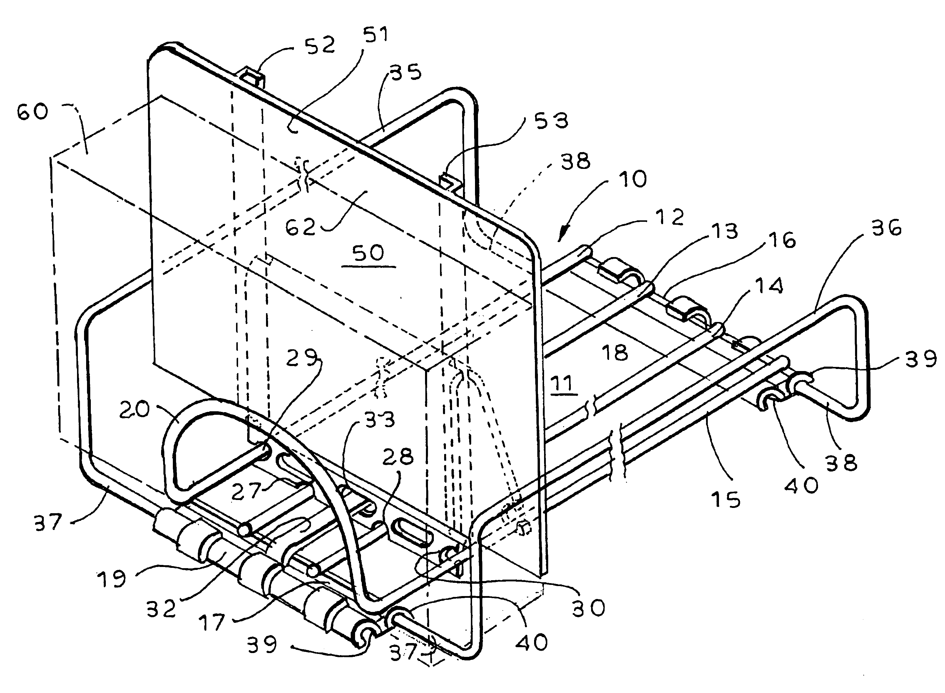
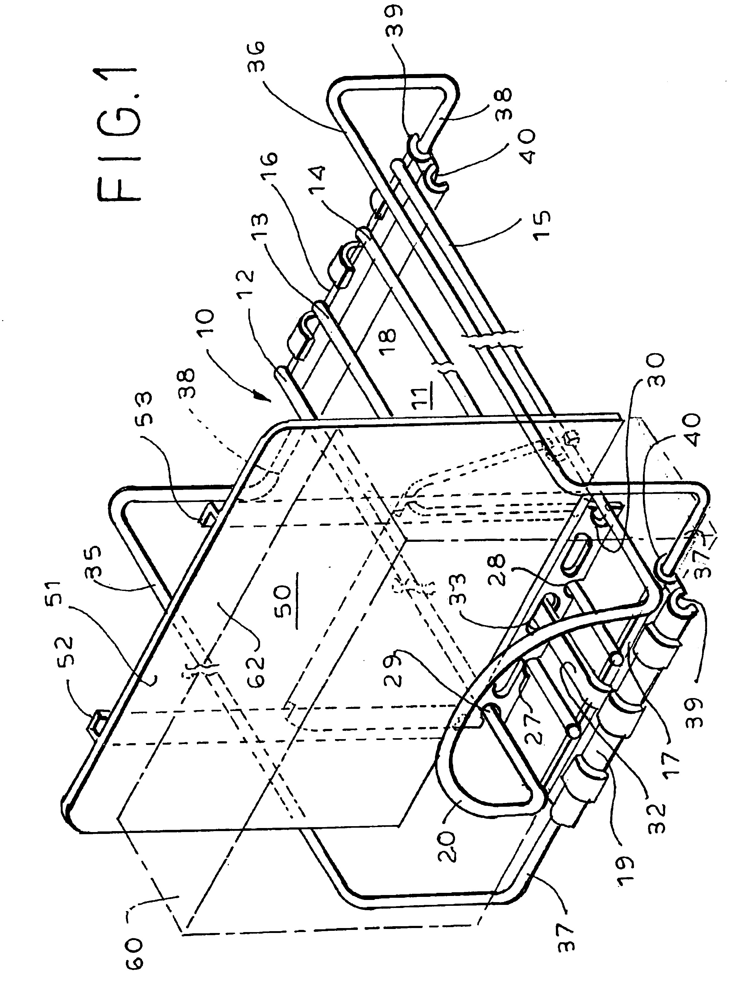
[0016]Referring now to the drawing, the reference numeral 10 designates generally a display rack of the type, for example, shown in co-pending application Ser. No. 10 / 323,461. The display rack includes a support base 11 which preferably comprises four wire support elements 12-15 arranged in a spaced-apart, parallel manner, extending in the front-to-back (longitudinal) direction. The end extremities of the wire supports 12-15 are welded to underlying transverse cross bars 16, 17 to provide a rigid, grid-like support base structure. Molded plastic base elements 18, 19 are formed with upwardly opening grooves (not specifically shown) to receive the respective cross bars 16, 17, preferably with a snap-in assembly action such that, once assembled, the base elements 18, 19 remain firmly attached to the cross bars 16, 17 unless intentionally removed therefrom.
[0017]In a preferred form of the invention, the opposite side support elements 12, 15 are integrally joined at the front by a suitab...
PUM
 Abstract
Description
Claims
Application Information