
Variable-stiffness wedge insert for runflat tire

a wedge insert and variable stiffness technology, which is applied to the sidewalls of tyres, vehicle components, transportation and packaging, etc., can solve the problems of reducing riding comfort, poor handling characteristics during normal inflated operation, and inability to achieve conventional inserts,

Inactive Publication Date: 2002-09-24
THE GOODYEAR TIRE & RUBBER CO
View PDF12 Cites 43 Cited by
  • Summary
  • Abstract
  • Description
  • Claims
  • Application Information

AI Technical Summary

Problems solved by technology

That is to say, the ride will be rougher and less comfortable due to the greater sidewall stiffness which arises from the greater rigidity imparted to the sidewall portions by the presence of the inserts.
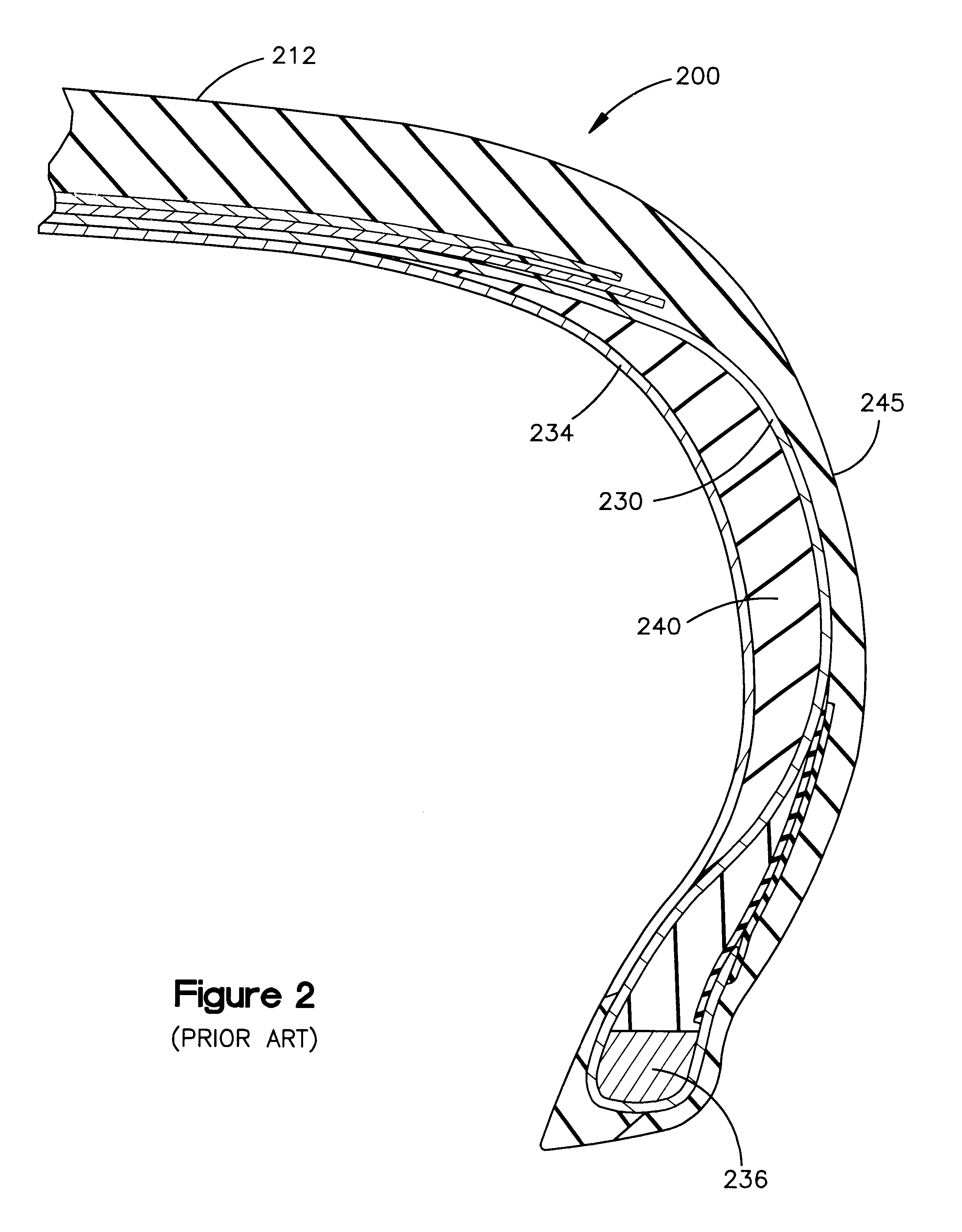
So, although it is desirable that the insert stiffness be very low during normal-inflated operation and very high during runflat operation, this cannot be achieved with conventional inserts, and the stiffness of conventional inserts is designed to be some compromise value in-between.
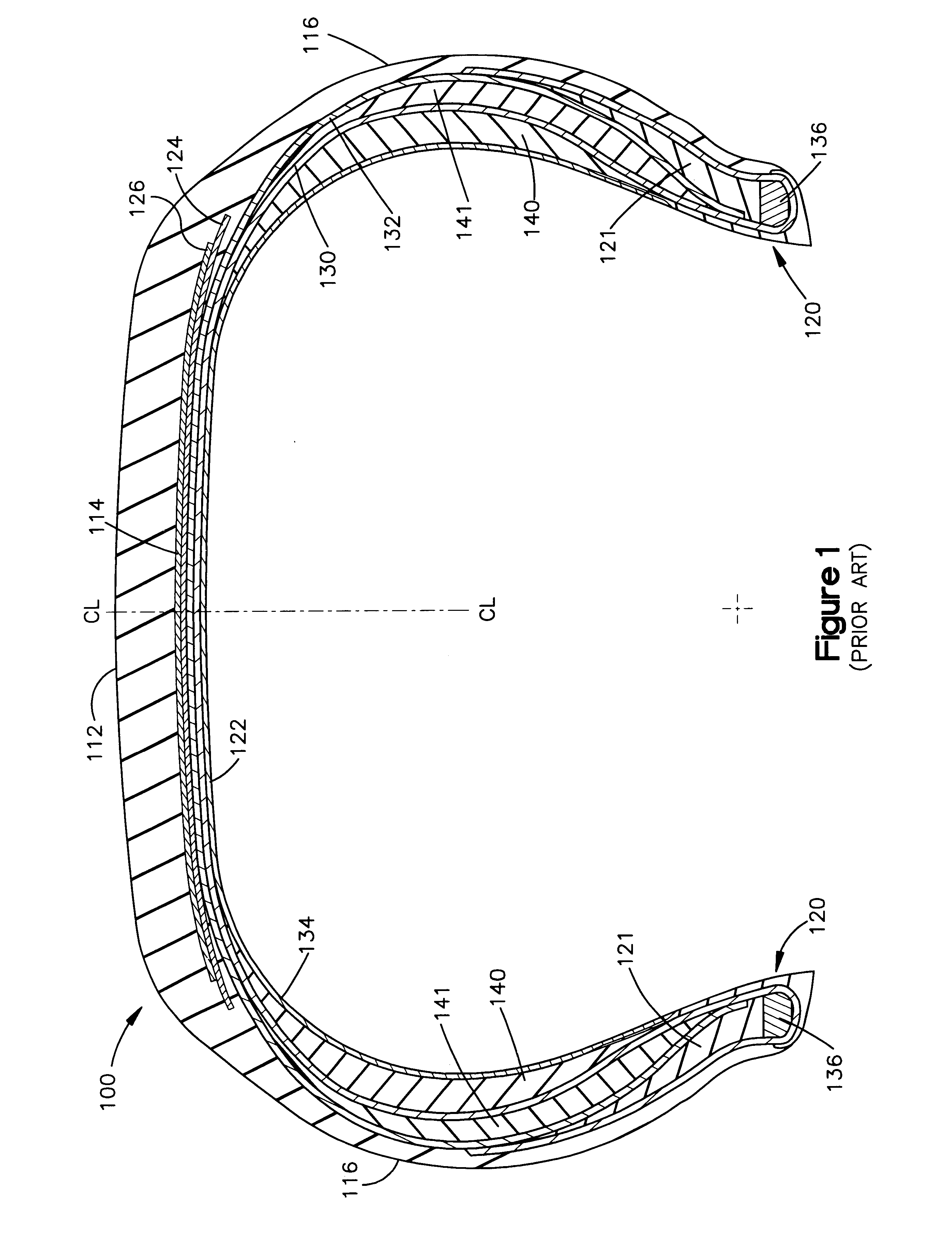
It can now be understood, specifically graphically, that the prior art designs resulted in a runflat radial tire that exhibits equal reinforcing rigidity to each sidewall during both normal inflated operation and during runflat operation, thereby providing reduced riding comfort and poor handling characteristics during normal inflated operation as well as rigid structural support during runflat operation.
Moreover, the prior art runflat radial tire contained inserts that generated heat during normal inflated high-speed operation and during runflat operation.
Finally, the prior art runflat radial tire had limited runflat operational service life and only adequate handling characteristics.

Method used


Image

  • Variable-stiffness wedge insert for runflat tire
  • Variable-stiffness wedge insert for runflat tire
  • Variable-stiffness wedge insert for runflat tire

Examples


second embodiment

FIG. 5A shows a schematic cross-section of a second embodiment of a circumferentially disposed insert 540 according to the present invention. The profile of insert 540 is shown in FIG. 5A as it would be in a normally inflated tire. The insert 540 is crescent-shaped in cross-section and comprises a somewhat semicircular elastomeric porous section 542 embedded in the axially-inner portion of the insert 540 surrounded by an elastomeric stiffer layer 544 (i.e. stiffer than the porous section 542) that comprises the remainder of the insert 540. The porous section 542 is attached to the stiffer layer 544 by any suitable means, such as cementing or overmolding one over the other. The substantially semicircular porous layer 542 is located at the vertically-center axially-inner portion of the insert 540, with its rounded edge facing axially outward. The insert 544 is bounded on its axially inner side by an innerliner 534 and on its axially outer side by a ply 530.

FIG. 5B shows the profile of...

third embodiment

FIG. 6A shows a fragmentary schematic cross-section of a third embodiment of a circumferentially disposed insert 640 according to the present invention. The profile of insert 640 is shown in FIG. 6A as it would be in a normally inflated tire. The insert 640 is crescent-shaped in cross-section and comprises a substantially triangular elastomeric porous section 642 embedded in the axially-inner portion of the insert 640 surrounded by an elastomeric stiffer layer 644 (i.e. stiffer than the porous section 642) that comprises the remainder of the insert 640. The porous section 642 is attached to the stiffer layer 644 by any suitable means, such as cementing or overmolding one over the other. The triangular porous layer 642 is located at the axially-inner portion of the insert 640, with one of its apexes pointing axially outward. The insert 644 is bounded on its axially-inner side by an innerliner 634 and on its axially-outer side by a ply 630.

FIG. 6B shows the profile of the insert 640 o...

fourth embodiment

FIG. 7A shows a fragmentary schematic cross-section of a fourth embodiment of a circumferentially disposed insert 740 according to the present invention. The profile of insert 740 is shown in FIG. 7A as it would be in a normally inflated tire. The insert 740 is crescent-shaped in cross-section and includes a cross-sectionally triangular elastomeric porous section 742 embedded in the radially-center axially-inner portion of the insert 740, affixed to a flexible inextensible hinge section ("hinge") 746 embedded in the axially-outer portion of the insert 740, and two stiff wedges 744A,744B (much stiffer than the porous section 742) that constitute the remainder of the insert 740. The porous section 742, the hinge section 746, and the stiff wedges 744A,744B are affixed together by a suitable means, such as overmolding each over the other(s). The insert 740 is bounded on its axially inner side by an innerliner 734 and on its axially outer side by a ply 730.

The triangular porous layer 742...


PUM


Abstract

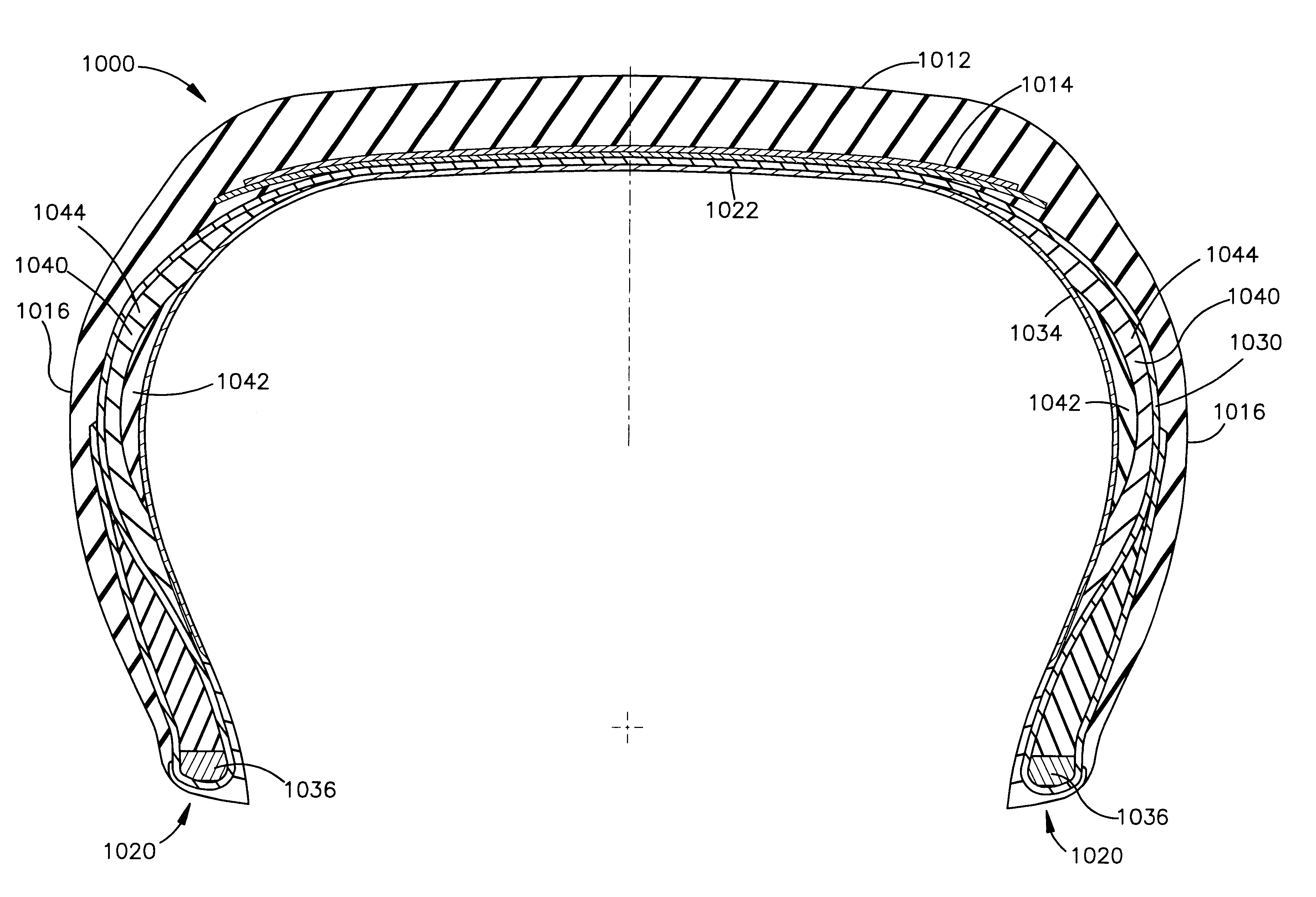
A pneumatic radial ply runflat tire 1000 for a vehicle has a tread 1012, a carcass 1022 comprising at least one radial ply 1030 and two sidewalls 1016 each reinforced by a circumferentially disposed crescent-shaped wedge insert. Each insert has an elastomeric porous section 1042 embedded in an elastomeric stiffer layer 1044 of the insert 1040. When the tire is normally inflated, the porous section 1042, and hence the insert as a whole, is flexible, thereby providing comfortable driving characteristics. Under runflat (deflated tire) conditions, the pores in the porous section 1042 collapse, and the porous section 1042 stiffens, and hence the insert as a whole becomes stiff enough to support the load of the vehicle.

Description

This invention relates to pneumatic radial-ply runflat tires and in particular to runflat tire construction wherein a sidewall wedge insert allows for sidewall flexibility under normal-inflated operating conditions yet provides high rigidity under deflated operating conditions.Various methods have been devised for enabling the safe continued operation of deflated or underinflated (flat) tires without damaging the tire further and without compromising vehicle handling while driving to where the tire can be changed. Loss of tire pressure can result from a variety of causes such as a deteriorated seal between the tire and rim or a tire puncture by a sharp object such as a nail.Pneumatic tires designed for continued operation under deflated or underinflated conditions are referred to as "extended mobility technology" tires or "EMT" tires. They are also called "runflat" tires, as they are capable of being driven in the flat condition. EMT (runflat) tires are designed to be driven in the ...

Claims


Application Information

Patent Timeline
IPC IPC(8): B60C17/00B60C13/00
CPCB60C17/0009B60C17/0027
Inventor COLANTONIO, LAURENTROESGEN, ALAIN EMILE FRANCOISCORVASCE, FILOMENO GENNARO
Owner THE GOODYEAR TIRE & RUBBER CO
Learn More