Connector

a technology of connecting rods and connectors, which is applied in the direction of coupling device connections, electrical apparatus, coupling protective earth/shielding arrangements, etc., can solve the problems of terminal fittings becoming obstacles, difficult to automate the process of delivering electric wires to their crimping location, and difficulty in pulling out electric wires

Inactive Publication Date: 2002-10-08
SUMITOMO WIRING SYST LTD
View PDF6 Cites 49 Cited by
  • Summary
  • Abstract
  • Description
  • Claims
  • Application Information

AI Technical Summary

Problems solved by technology

Consequently, these terminal fittings become an obstacle after they have been crimped to the ends of the electric wires, in that they prevent the ferrite cores from being fitted.
However, when the ferrite cores are in an attached state with the outside of the electric wires, it is difficult to automate the process of delivering the electric wires to their crimping location and of pulling out the electric wires which have been crimped.

Method used


Image

  • Connector
  • Connector
  • Connector

Examples


Embodiment Construction

An embodiment of the present invention is described below with the aid of FIGS. 1 to 9.

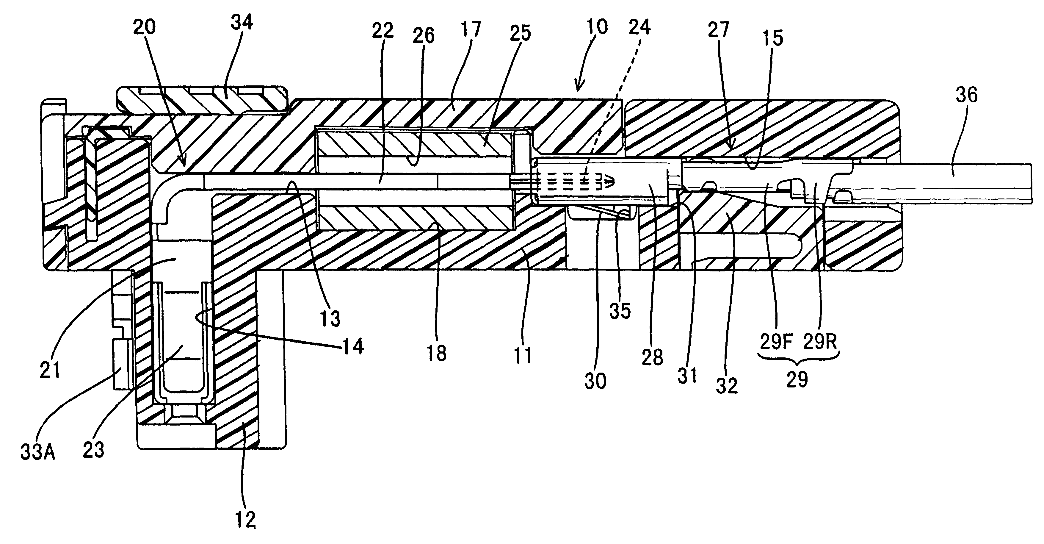
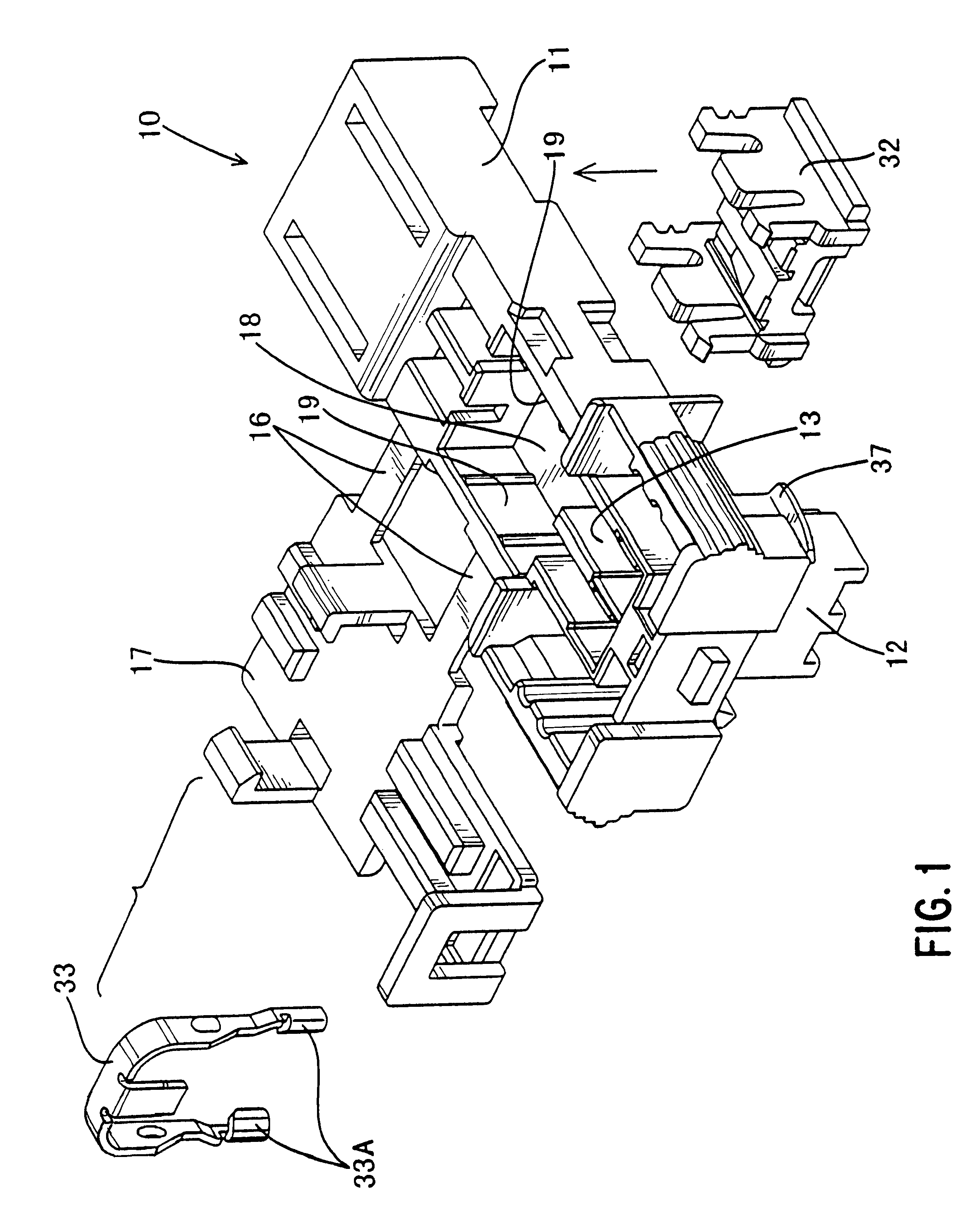
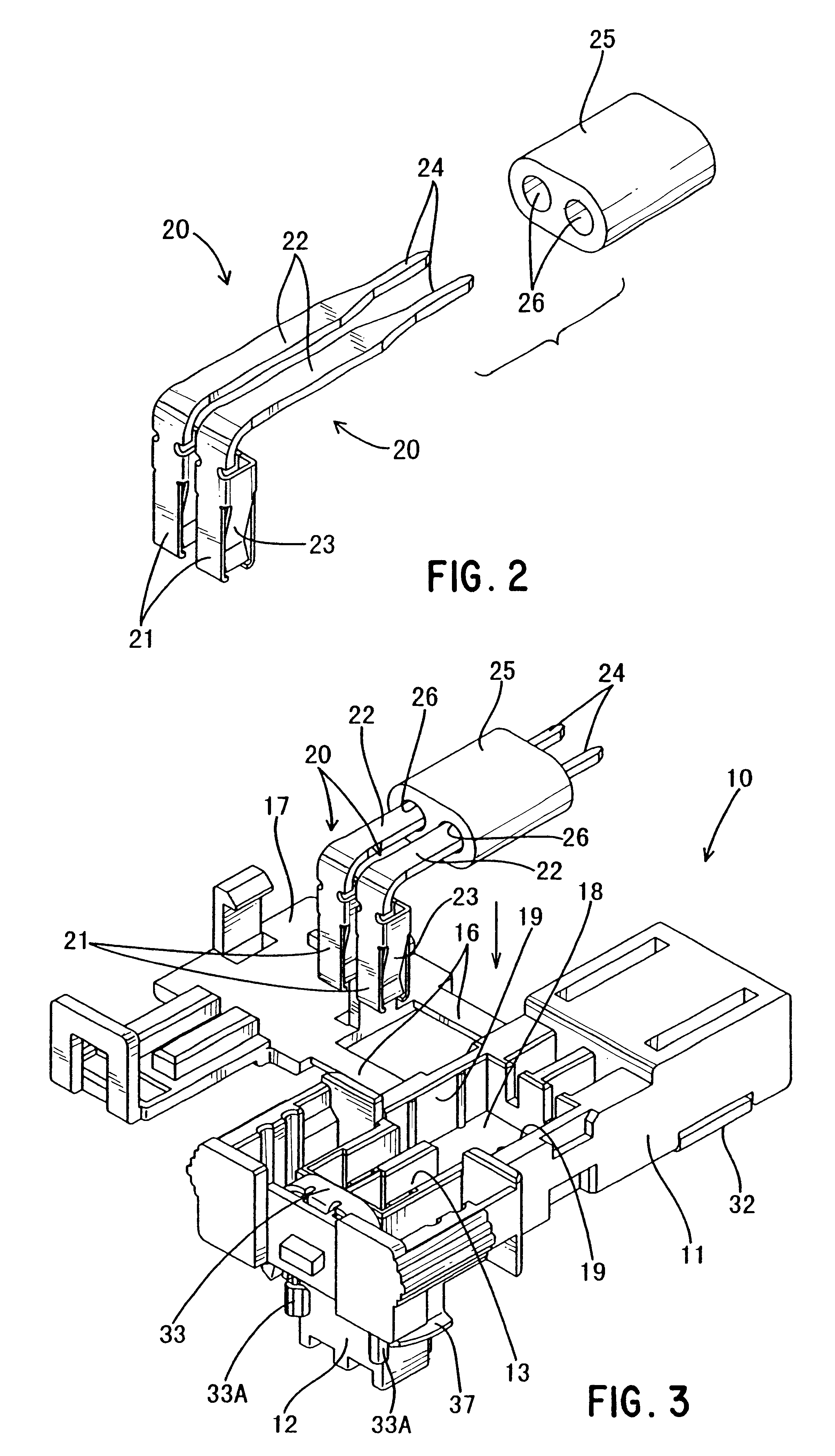
A connector of the present embodiment is formed from a housing 10, two joint terminal fittings 20, a ferrite core 25, and two electric wire terminal fittings 27.

The housing 10 is made from plastic, and is composed from a main body 11 which extends in an anterior-posterior direction, and a fitting member 12 which protrudes downwards from an anterior end of the main body 11. The fitting member 12 fits with a corresponding connector (not shown). First, second and third cavities 13, 14 and 15, for housing the joint terminal fittings 20, the electric wire terminal fittings 27, and the ferrite core 25, are formed in the housing 10. The first cavities 13 extend a long the anterior-posterior direction of the main body 11, occupy approximately two thirds of the region of the housing 10 in the anterior-posterior direction, and open out onto an upper face of this housing 10. This opening portion at the upper...


PUM


Abstract

The invention provides a connector with improved operability during the joining operation of electric wires and terminal fittings, and during the attachment of ferrite cores.A connector is provided with conducting members 20 capable of making contact with corresponding terminal fittings, a ferrite core 25 which is attached from the exterior to the conductive members 20, electric wire terminal fittings 27 capable of making contact with electric wires 36 and the conducting members 20, and a housing 10 which houses all of the above. The conducting members 20, to which the ferrite core 25 is attached, are formed separate from the members (the electric wire terminal fittings 27) that connect with the electric wires 36. Consequently, an automated device is able to connect the electric wire terminal fittings 27 and the electric wires 36.

Description

The present invention relates to an electrical connector.BACKGROUND TO THE INVENTIONAn air-bag electrical circuit of an automobile typically has a ferrite core provided thereon in order to reduce noise along this circuit. One example of this is described in JP 11-144796. In this example, ferrite cores are attached to the exterior of electric wires, at a location close to the ends thereof, and terminal fittings are crimped to these electric wires at locations which are closer than the ferrite cores to the ends. The terminal fittings and the ferrite cores are housed, together with the ends of the electric wires, within a connector housing.In the connector described above, in which the ferrite cores are attached to the exterior of electric wires, the outer dimension of the terminal fittings is greater than that of the electric wires. Consequently, these terminal fittings become an obstacle after they have been crimped to the ends of the electric wires, in that they prevent the ferrite ...

Claims


Application Information

Patent Timeline
Patent Type & Authority Patents(United States)
IPC IPC(8): H01R13/719H01R13/7193H01R13/7197
CPCH01R13/7197
Inventor NIMURA, KAZUHIKO
Owner SUMITOMO WIRING SYST LTD
Why Eureka
Try Eureka