Monolithic composite wing manufacturing process

a manufacturing process and monolithic composite technology, applied in sandwich constructions, transportation and packaging, other domestic articles, etc., can solve the problems of large manual labor, large number of parts, and low load transmission efficiency of small amount of composite materials

Inactive Publication Date: 2001-02-20
APPA KARI
View PDF5 Cites 233 Cited by
  • Summary
  • Abstract
  • Description
  • Claims
  • Application Information

AI Technical Summary

Problems solved by technology

That means, a small amount of composite material can support large forces when properly used.
The disadvantages of the built-up fabrication process are the involvement of extensive manual labor and the need to assemble a large number of parts.
Another serious drawback of the built-up process is that the load transmission efficiency is very low, because, the mechanical fasteners induce large stresses leading to delamination and breakdown of structural members.
However, the same fabrication process cannot be applied to manufacture aircraft wing structures because of higher bending and torsion stiffness requirements.
This fabrication process does not provide sufficient torsion stiffness for aircraft wings.
Moreover, it is not possible to inflate aircraft wing cells to conform to the airfoil shape.
This is the major drawback of this method.
A large number of fasteners are required to attach the skins to the honeycomb spars.
1. the structure is weak in torsion, because the skins and spars are joined by means of chemical glue that is weak in shear,
2. spar-skin joining process involves many elements and consequently many manual operations,
3. removable mandrels are required that increases manufacturing cost,
4. automation is applied only at the final wrapping and bonding process, while other operations involve intensive manual labor.
Hence, the art governed by the U.S. patent 4,565,595 yields a torsionally weaker structure and also increases manufacturing cost due to several manual operations in the wing assembly.
No effort has been made to take advantage of composite fiber directional strength and minimum weight considerations.
This is a novel concept except that it produces a non-optimal structure having a lower value of strength to weight ratio.
Moreover, this construction results in lesser fuel volume and becomes difficult to manage the change in center of gravity as the fuel is dispensed in flight.

Method used


Image

  • Monolithic composite wing manufacturing process
  • Monolithic composite wing manufacturing process
  • Monolithic composite wing manufacturing process

Examples


Embodiment Construction

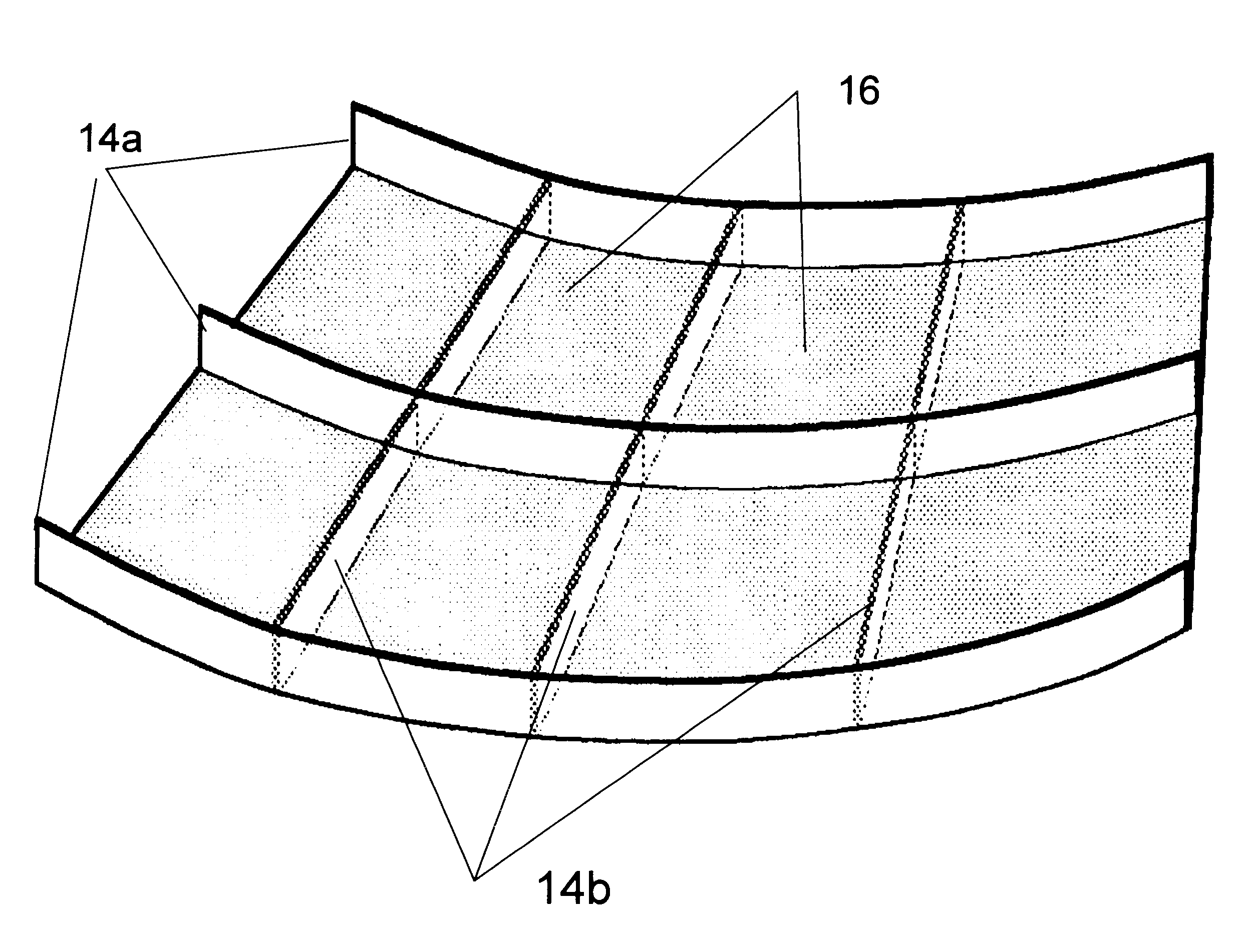
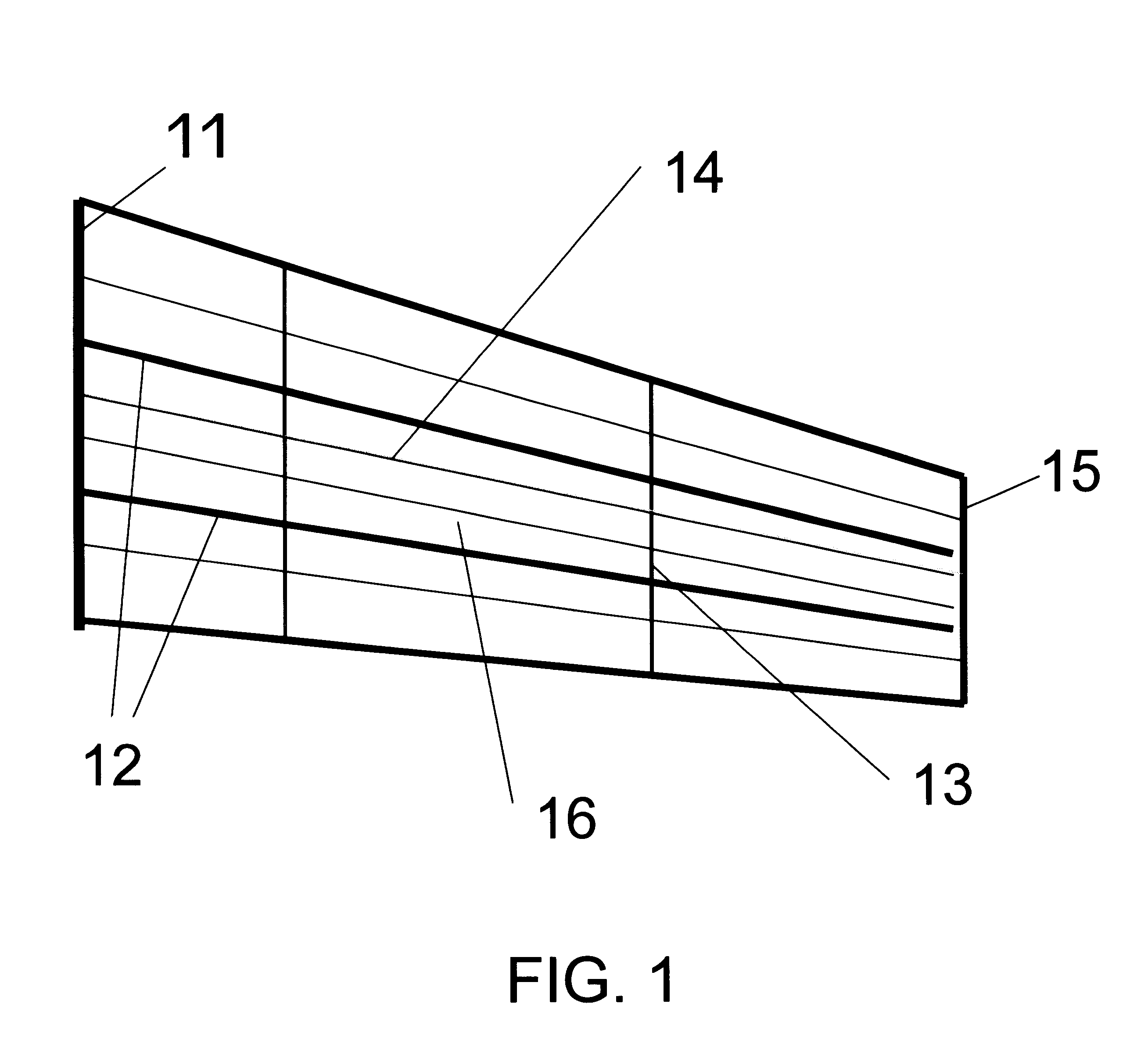
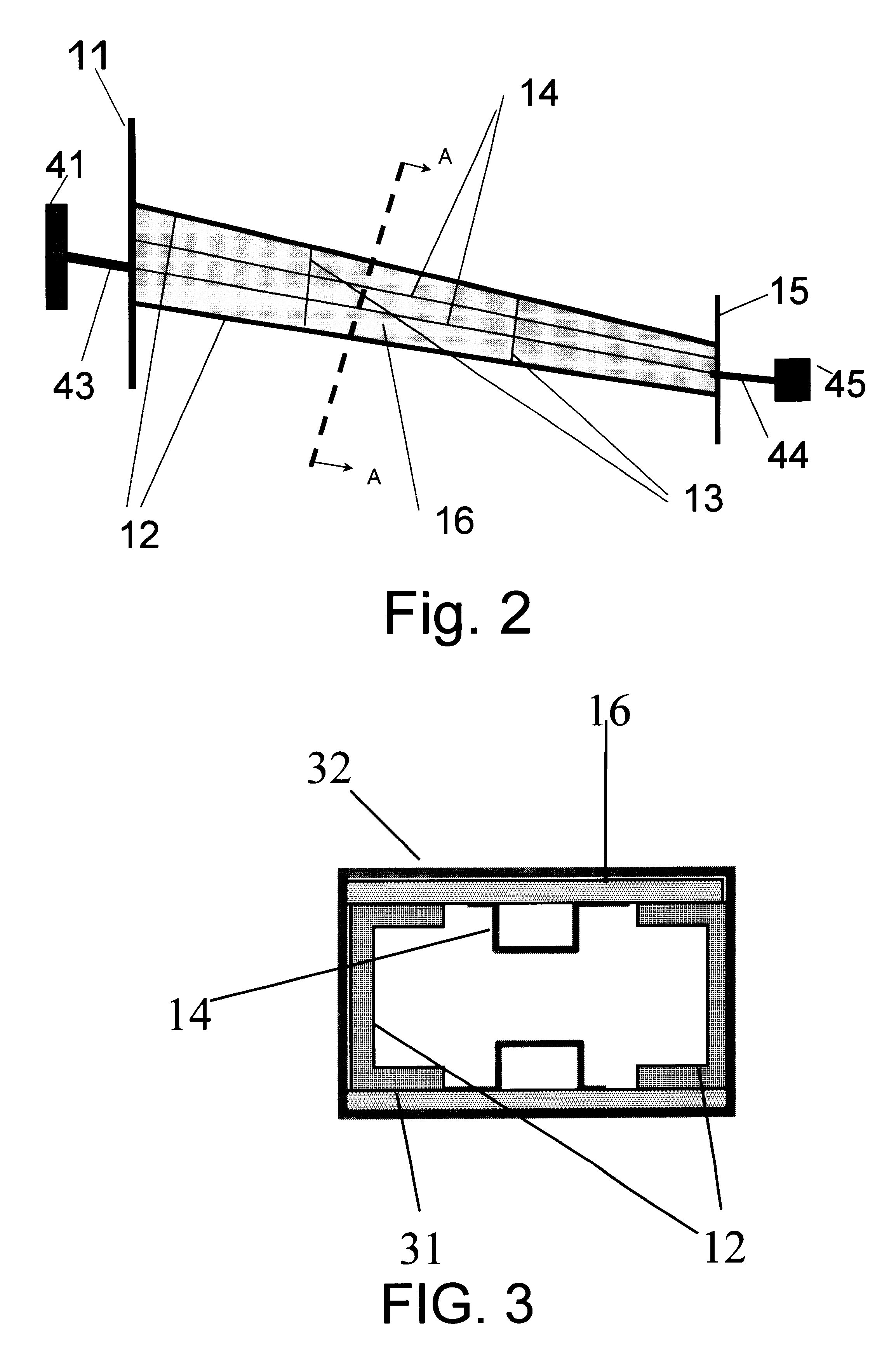
Referring now to FIG. 1, which generally illustrates a typical embodiment of a monolithic composite wing assembly of an aircraft. The plan view of the semi-span wing shows a framework of plurality of U-channel shaped spars 12 and stringers 14 disposed in the longitudinal direction extending from the wing root to the wing tip. Similarly shaped rib-lets 13 are disposed in nearly perpendicular directions to said spars. In addition, several layers of pre-pregged composite tows 32 (shown in FIG. 3) comprising thousands of carbon or boron fibers are wrapped and adhesively bonded around and along plurality of mandrel-like wing box cells. Specific details of the drawings and the fabrication processes are described next.

FIG. 2 illustrates one embodiment of the present invention that has a dual role of a mandrel as well as an integral member of a wing structure. A mandrel is a devise to provide an airfoil shaped wing surface. The prior arts uses specially made removable mandrels. Such mandrel...


PUM

PropertyMeasurementUnit
widthaaaaaaaaaa
pressureaaaaaaaaaa
temperatureaaaaaaaaaa

Abstract

A method of manufacturing a monolithic composite wing without using mechanical fasteners is described. The process begins with the formation of a center wing box in combination with a pair of spars, riblets and a pair of skin-molds including the wrapping and binding of the box by means of resin impregnated composite tapes. Next, additional cells are adjoined contiguously on either side of the current framework and an overlap wrapping and bonding process is continued around the current framework. The overlap wrapping and binding procedure provides increased torsion stiffness and reduced structural weight. All cells up to the leading and trailing edges will be included in the assembly process. Conduits to convey fuel, hydraulic fluid and electrical wiring will also be installed in designated cells. Finally, the completed wing will be cured in an autoclave under uniform pressure and temperature.

Description

Not ApplicableNot ApplicableREFERENCE TO A MICROFICHE APPENDIXNot Applicable1. Field of InventionThis invention describes a manufacturing process for a monolithic composite wing, more particularly, that reduces manufacturing cost, increases structural strength, enhances structural integrity and reduces structural weight. In another manner of speaking, this invention provides an automated fabrication method that increases production rate and reduces the life cycle cost of the aircraft.2. Description of Prior ArtComposite materials are made of thin fibers, not necessarily limited to carbon, boron or kevlar, imbedded in an epoxy like resin. These composite materials possess, generally speaking, a high strength to weight ratio. That means, a small amount of composite material can support large forces when properly used. Hence, composite materials play a significant role in aerospace industries as well as in other commercial products.Heretofore, the aircraft wing manufacturing processes ...

Claims


Application Information

Patent Timeline
Patent Type & Authority Patents(United States)
IPC IPC(8): B29C70/04B29C70/34B29C70/38B64F5/00B64C3/00B64C3/20
CPCB29C70/32B29C70/342B29C70/386B64C3/20B64F5/0009Y02T50/433B29L2031/3085B64F5/10Y02T50/40
Inventor APPA, KARI
Owner APPA KARI
Why Eureka
Try Eureka