Apparatus and methods for transmission line based electric fence insulation

Inactive Publication Date: 2012-07-19
SHAN XUEKANG +1
View PDF3 Cites 224 Cited by
  • Summary
  • Abstract
  • Description
  • Claims
  • Application Information

AI Technical Summary

Benefits of technology

[0007]FIG. 1 is a perspective view of the insulator of this invention. Rain shed 11 sheds wire clamps 12. Wire clamps 12 clamp wire pair 14. Rain water divert guides 13 prevent rain water from f

Problems solved by technology

When rain water accumulates on the wire, it may flow towards the wire clamp due to the

Method used


Image

  • Apparatus and methods for transmission line based electric fence insulation
  • Apparatus and methods for transmission line based electric fence insulation
  • Apparatus and methods for transmission line based electric fence insulation

Examples


Embodiment Construction

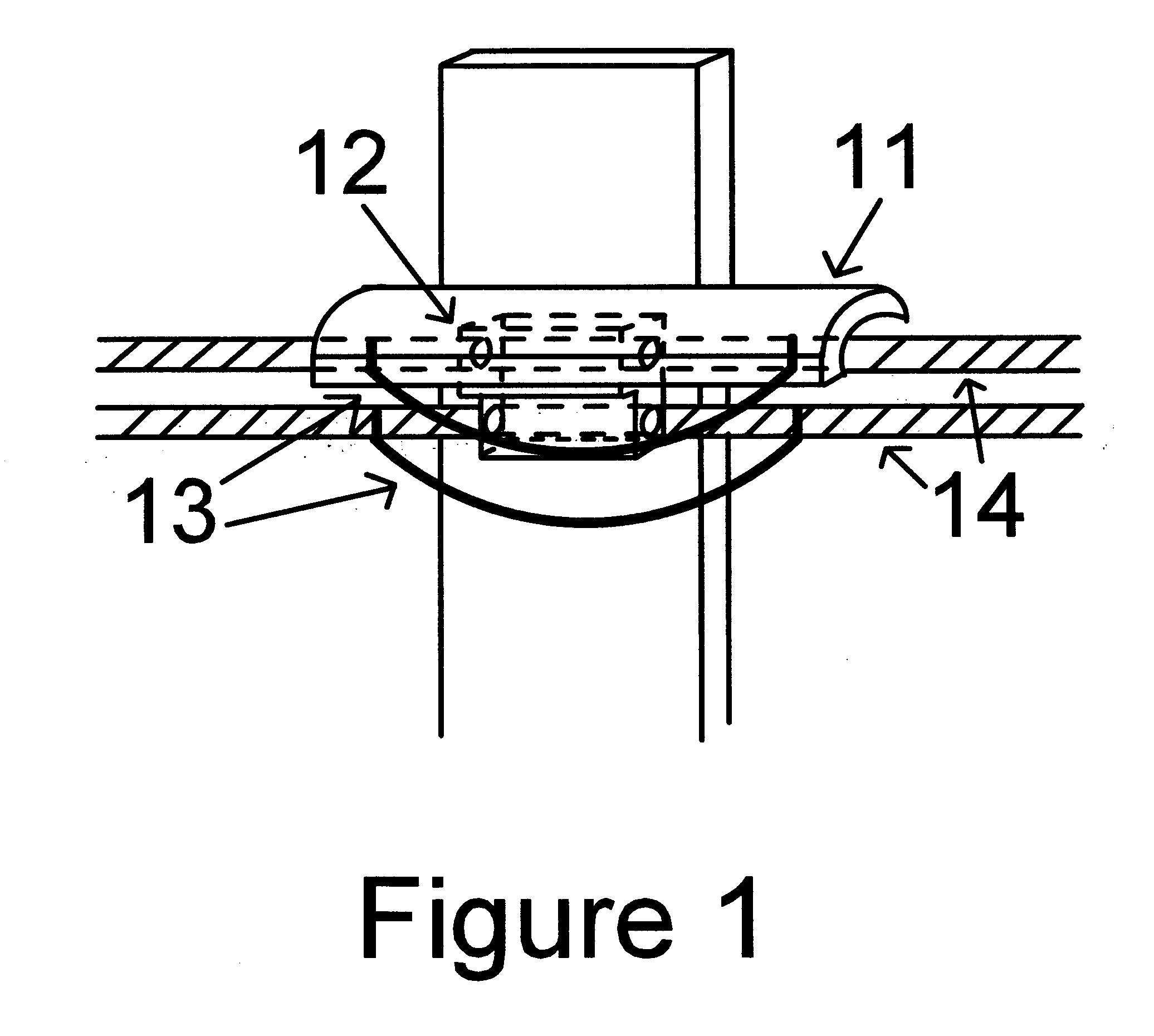
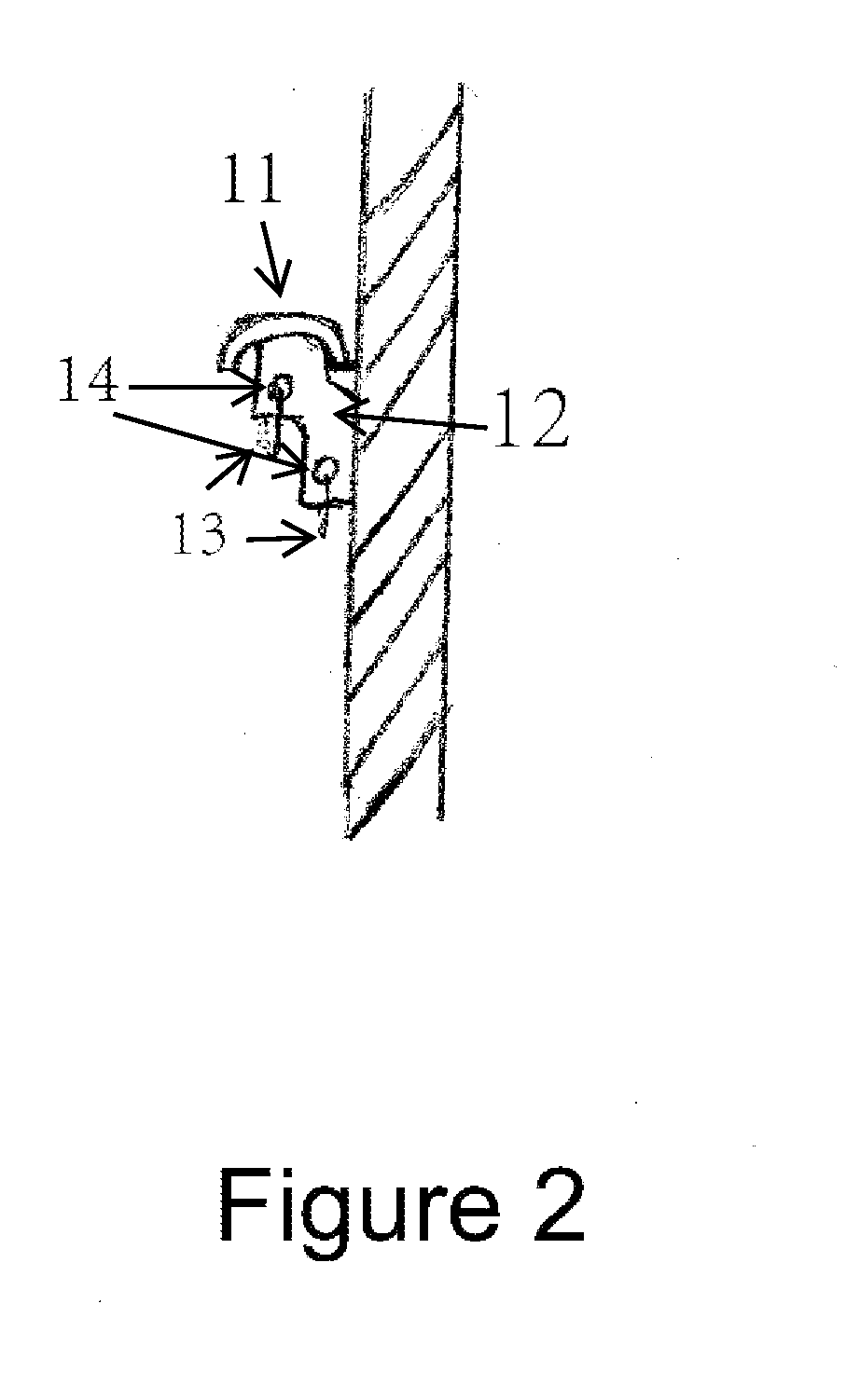
[0010]FIG. 1 shows the insulator of this invention. The insulator is mounted on the post via holes and bolts. The wire pair are attached to the insulator by clamps and bolts. The two wires have an offset horizontally such that rain water will not drip into a continuous line between the two wires to form a resistive load between the wire pair. When rain water collected on the wire flows towards the wire clamp, the rain water divert guide guides the water to the bottom of the guide and keeps it from wetting the wire / wire clamp contact point.

[0011]A DC or a low frequency AC power source is used to heat the transmission line when necessary. The transmission line based electric fence works using high frequency short electric pulses. Therefore low-pass and high-pass electric filters that have different impedance at different frequencies can be used to supply electric current to heat the wires without affecting the normal operation of the electric fence. In FIG. 3, inductor 23, capacitor 2...


PUM


Abstract

Apparatus and methods for wire insulation in transmission line based electric fence are described in this invention. An insulator holds a wire pair that form the transmission line in its wire clamps. The insulator has a rain shed that sheds the wire clamps from getting wet by rain water. The insulator also has a pair of rain water divert guides that guide rain water accumulated on the wire to flow to the guide instead of to the wire clamps. This invention also describes a wire heating method that uses electric current to heat the fence wires such that the wire/wire clamp contact point will be kept dry and ice, snow accumulated on fence wires will be melted. Performance of the transmission line based electric fence can thus be greatly improved in advert weather conditions.

Description

BACKGROUND OF THE INVENTION[0001]Electric fences are widely used for security purposes and for animal control. Most electric fences use metal wires to surround the area to be protected, and the metal wires are changed to a high voltage by energizers. When touched, this high voltage on the wires will repel or deter the intruder or animal. And an alarm signal is also triggered by the touch on the wire. But this type of electric fences can not give information of the location of the intrusion.[0002]A recently filed patent application (application Ser. No. 12 / 954,704) describes a new type of electric fence, which is based on transmission line. A pair of metal wires are installed on the fence, which is equivalent to a common transmission line with a characteristic impedance. A short electric pulse is sent down the transmission line. If an intruder touches the transmission line, he adds a load impedance at this point of the line. According to the transmission line theory, a portion of the...

Claims


Application Information

Patent Timeline
IPC IPC(8): H05B1/02H01B17/16
CPCH01B17/145H01B17/54
Inventor SHAN, XUEKANGHAO, JIN
Owner SHAN XUEKANG
Why Eureka
Try Eureka