Tire filing method and apparatus adaptable to different sizes of tires

a filing method and tire technology, applied in the field of tire filing method and tire filing apparatus adaptable to different sizes of tires, can solve the problems of inability to readily adapt the conventional tire filling station described above is not suitable for use, and the capacity of the known tire filling station to handle wheel/tire combinations of different diameters is limited

Inactive Publication Date: 2002-10-22
SCHENCK ROTEC GMBH
View PDF9 Cites 39 Cited by
  • Summary
  • Abstract
  • Description
  • Claims
  • Application Information

AI Technical Summary

Problems solved by technology

The above described conventional tire filling station is not suitable for use in tire mounting production lines in which wheels having respective wheel rims and / or tires of greatly varying sizes are to be mounted.
In other words, such a known tire filling station is not readily adaptable for filling wheel / tire combinations of greatly differing sizes in succession, but instead is generally only suitable for the series production of a single size of wheel / tire combinations.
Particularly, the capacity of the known tire filling station to handle wheel / tire combinations of different diameters is limited because the diameter of the support plate is limited or confined by the dimensions of the transport apparatus.
Also, the size capacity of the known tire filling station is limited by the diameter of the tire filling bell.
For these reasons, wheel / tire combinations having a larger diameter than intended for the respective tire filling station cannot easily be mounted or filled on such a tire filling station.
The seal ring is subject to wear and damage, so that it requires a high degree of monitoring and maintenance.
Especially when a seal ring is used in connection with wheel rims of present-day modern design, in which the major wall or bowl of the rim protrudes laterally outwardly beyond the rim lip, the seal ring will improperly contact the protruding bowl wall of the wheel rim at an angle relative to the wheel rim lip.
For these reasons, it has been found in practice that such a tire filling bell has very little flexibility or adaptability for use with a tire size mix.
All of these problems lead to additional efforts and costs in carrying out the tire filling process.
On the other hand, if the tire filling bell is not equipped with a seal ring, the major disadvantage is the substantially higher consumption and waste of pressurized air, because the entire interior space of the wheel rim must be filled with pressurized air during each filling cycle, in the manner as described above.

Method used


Image

  • Tire filing method and apparatus adaptable to different sizes of tires
  • Tire filing method and apparatus adaptable to different sizes of tires
  • Tire filing method and apparatus adaptable to different sizes of tires

Examples


Embodiment Construction

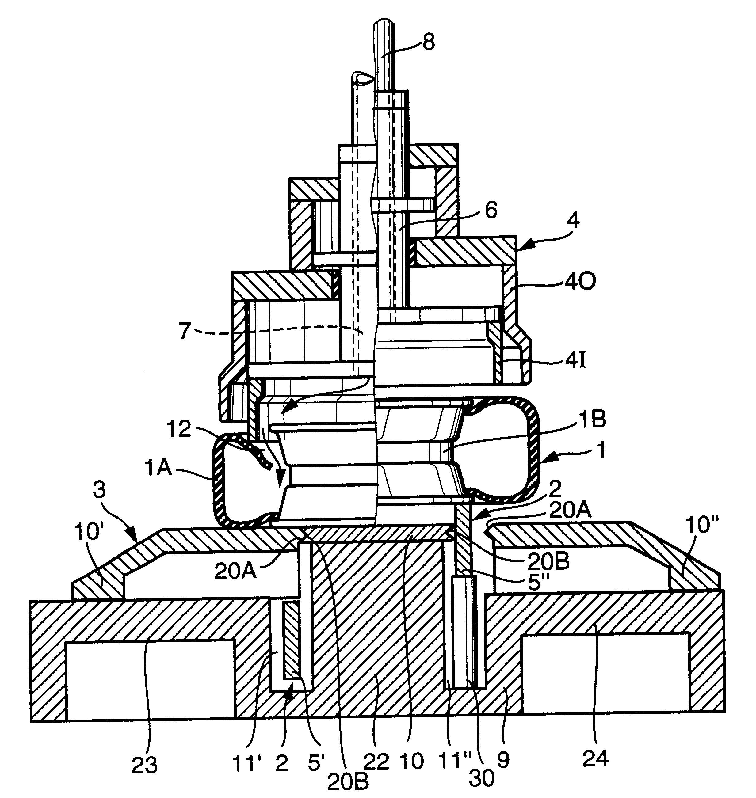
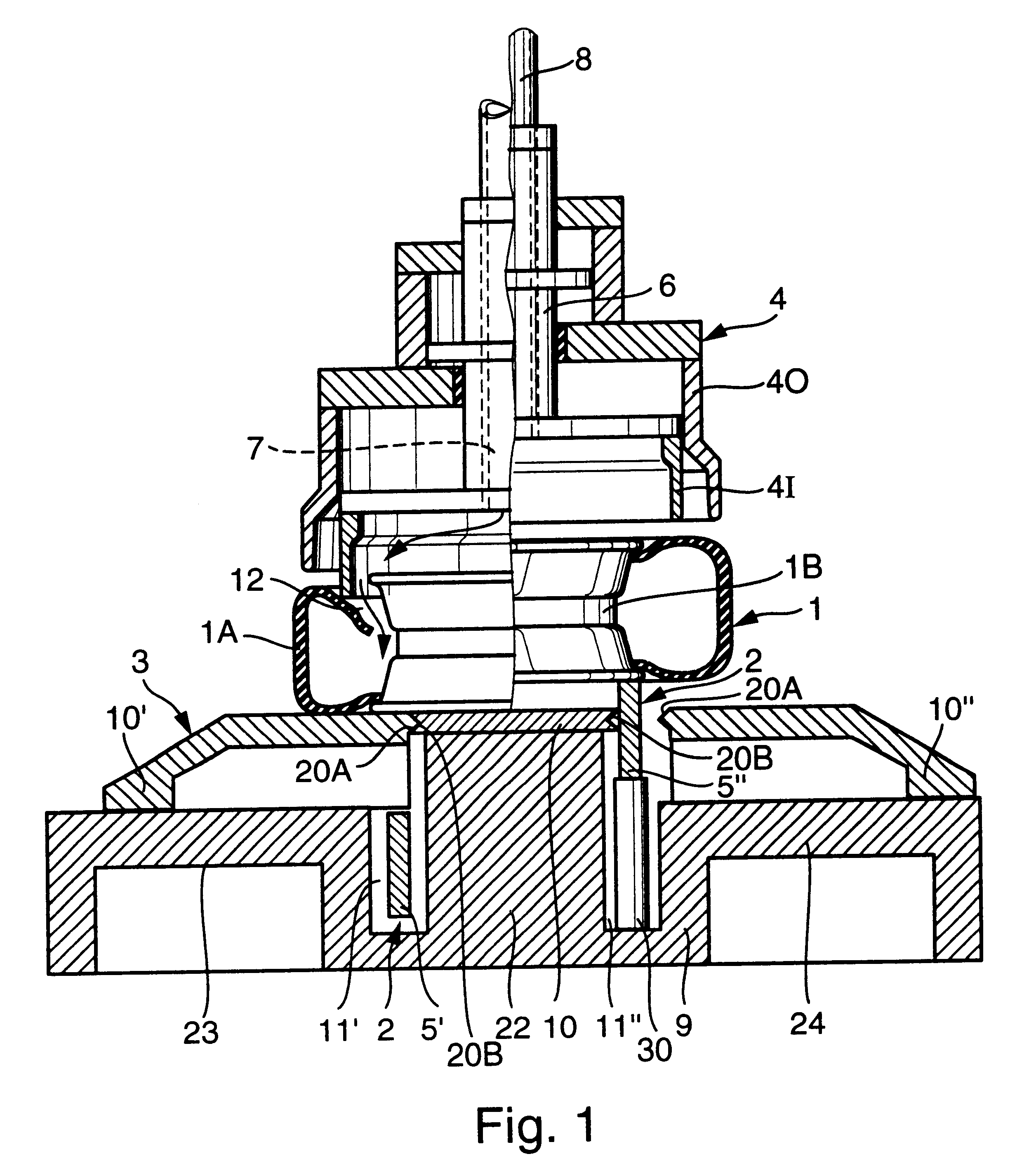
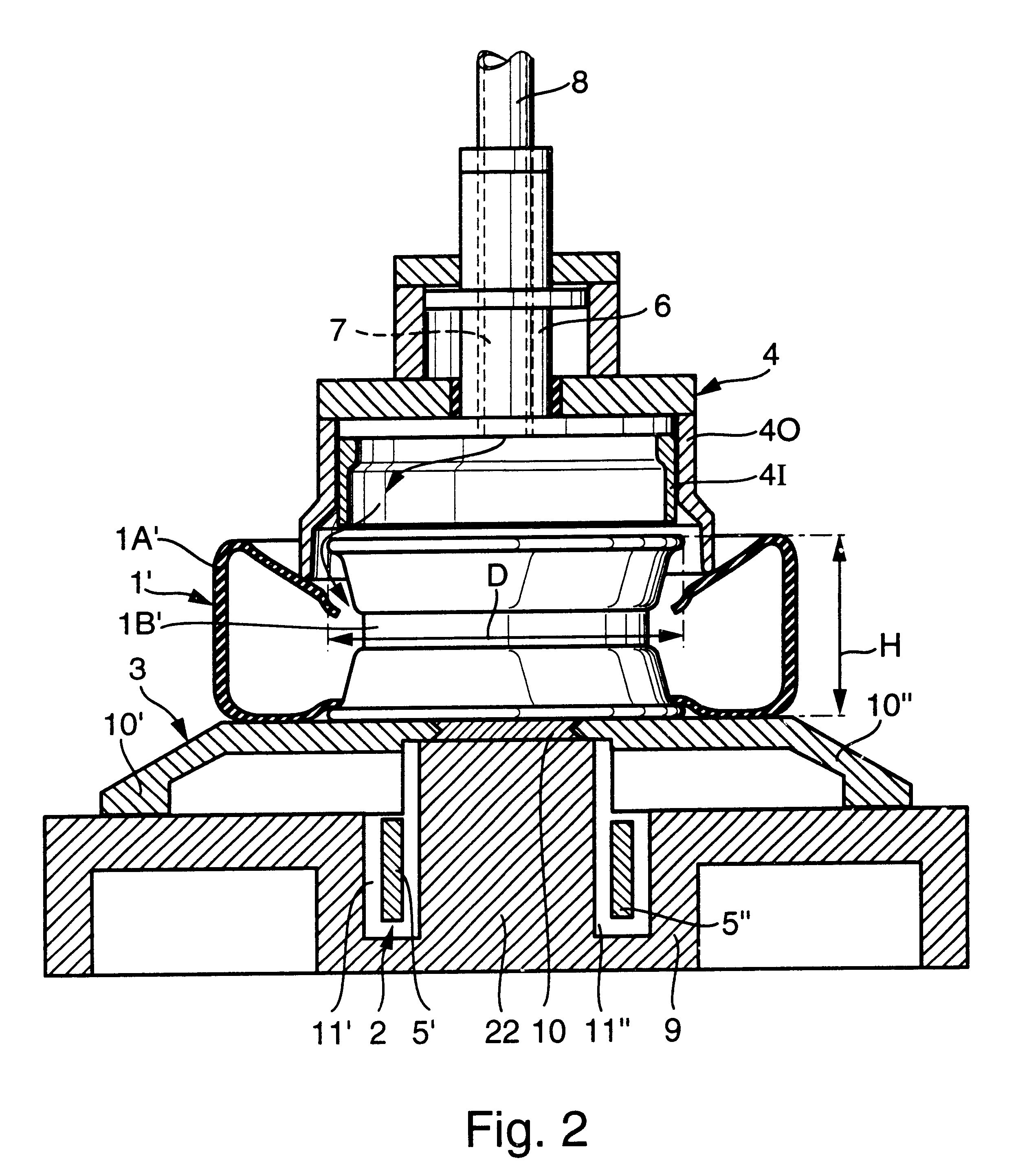
A tire 1A is loosely mounted on a wheel rim 1B in a tire mounting station (not shown) in any conventionally known manner, to form thereof a wheel / tire combination 1, which is then transported in the non-pressurized state, by means of the transport apparatus 2, from the tire mounting station to the tire filling station shown in FIG. 1. There, the wheel / tire combination 1 is then supported on a support and seal arrangement 3 of the filling station. The filling station further includes a tire filling bell or dome 4 through which pressurized air is provided to fill the tire. After the tire has been inflated, the transport apparatus 2 further transports the filled wheel / tire combination 1 away from the tire filling station to a subsequent unbalance measuring or balancing station. These stations can be respectively embodied as individual modules or separate stations that each respectively comprise a separate or individual machine frame. Alternatively, a single common machine frame can be ...


PUM


Abstract

A pneumatic tire filling station includes a support and seal arrangement on which one side wall of the tire is supported and sealed, and a tire filling bell that presses and seals against the opposite side wall of the tire and then supplies pressurized air into the tire. The filling bell includes outer and inner rings that are concentrically slidable relative to each other. One of the rings is selected for the filling operation depending on the size of the tire. The support and seal arrangement includes plural plate members that are joined and sealed together to form a continuous support and seal surface, or moved laterally apart to allow a transport apparatus to carry and support the mounted tire from underneath. The tire filling station is adaptable to different models and sizes of mounted tires even in a mixed process flow, in an automated manner.

Description

This application is based on and claims the priority under 35 U.S.C. .sctn.119 of German Patent Application 100 07 019.1, filed on Feb. 16, 2000, the entire disclosure of which is incorporated herein by reference.The invention relates to a tire filling station for filling pneumatic tires such as a motor vehicle tire in the form of a wheel / tire combination comprising a tire mounted on a wheel rim. The tire filling station includes a transport apparatus that transports the wheel / tire combination to a filling stand, including a tire filling dome or bell and an oppositely arranged support and seal arrangement, as well as means for moving at least one of the wheel / tire combination and the transport apparatus relative to each other in a direction perpendicular to the transport plane. A respective wheel / tire combination is received between the tire filling bell and the support and seal arrangement, which respectively contact and cooperate with the outer side walls of the tire, so as to fil...

Claims


Application Information

Patent Timeline
Patent Type & Authority Patents(United States)
IPC IPC(8): B60C25/00B60C25/05B60C25/135
CPCB60C25/05B60C25/145B60C25/135Y10T137/3584
Inventor RONGE, HEINZROGALLA, MARTINLIPPONER, GEORG
Owner SCHENCK ROTEC GMBH
Why Eureka
Try Eureka