Position sensor and housing therefor

a technology of position sensor and housing, which is applied in the direction of measurement gauge, measurement apparatus components, instruments, etc., can solve the problems of inability to provide a sufficiently sturdy grip on the sensor, inability to accurately measure, and inability to operate the movable member of the sensor, so as to reduce the down time of the gauge or equipment during the sensor chang

Inactive Publication Date: 2002-12-10
APPLIED COMPOSITES
View PDF20 Cites 21 Cited by
  • Summary
  • Abstract
  • Description
  • Claims
  • Application Information

AI Technical Summary

Benefits of technology

The depth of the flange position within the receiving housing, and the relative axial position of the flange along the body of the sensor are toleranced such that when an existing sensor is removed, and the existing sensor replaced by the insertion of another sensor, the replacement sensor exhibits an inserti

Problems solved by technology

Clamping and set screw attachment mechanisms have significant problems when used with many of the mechanical and electronic sensors used in today's equipment and products, because such attachment mechanisms can exert sufficient force on the sensor to pinch or distort the sensor, thereby causing inaccurate readings or else making the movable member of the sensor inoperable due to seizure or unreliable due to increased frictional resistance to the movement of the movable member caused by the pending forces of the attachment means.
Prior known ball detent mechanisms, although allowing quick removal of the sensor, have not provided a sufficiently sturdy grip on the sensor to assure that the sensor is maintained in a consistent and accurate location.
Few if any commercially available linear sensors are provided in a condition ready for attachment by use of a bol

Method used


Image

  • Position sensor and housing therefor
  • Position sensor and housing therefor
  • Position sensor and housing therefor

Examples


first embodiment

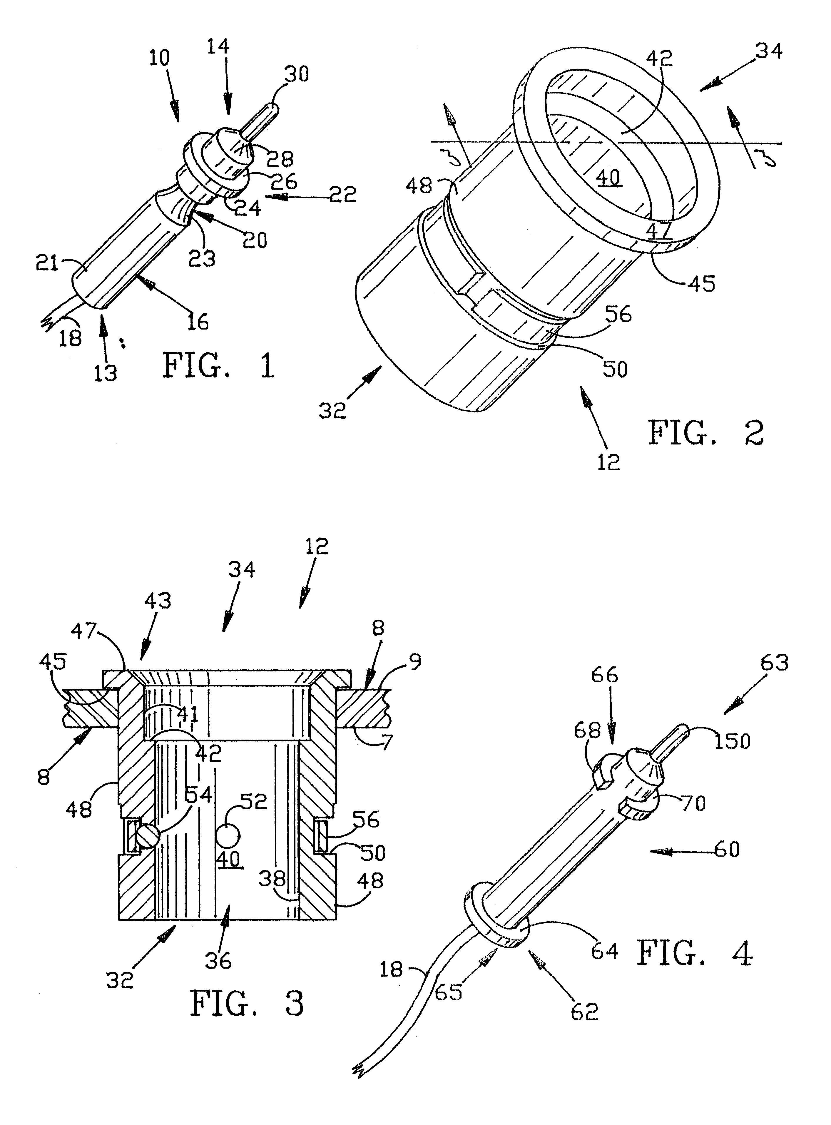
a sensor mechanism that includes a sensor 10 and a generally cylindrical sensor housing 12 is shown in FIGS. 1-3 and 9-11. The sensor housing 12 is designed for being inserted into an aperture of a test fixture 8 that is used in industrial processes, such as the manufacture of automotive glass, to test the manufactured item (e.g. the window glass) to ensure that the size and shape of the manufactured item fits within those tolerances specified by the purchaser of the manufactured item, e.g. the manufacturer of the automobile.

The test fixture 8 usually comprises a platform having an upper side (outer) surface 9 that is shaped to correspond generally with one of the surfaces of the manufactured item. The test fixture 8 also includes a lower (inner) side surface 7 that defines a hollow interior of the fixture 8. The sensor housing 12 is inserted through an aperture in the fixture 8 and includes means to engage the upper side surface 9 of the fixture 8, to prevent the sensor housing 12 ...

second embodiment

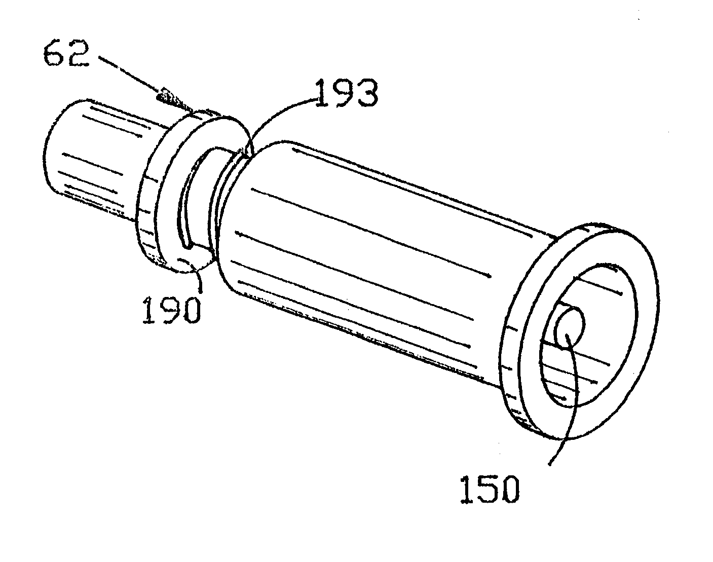
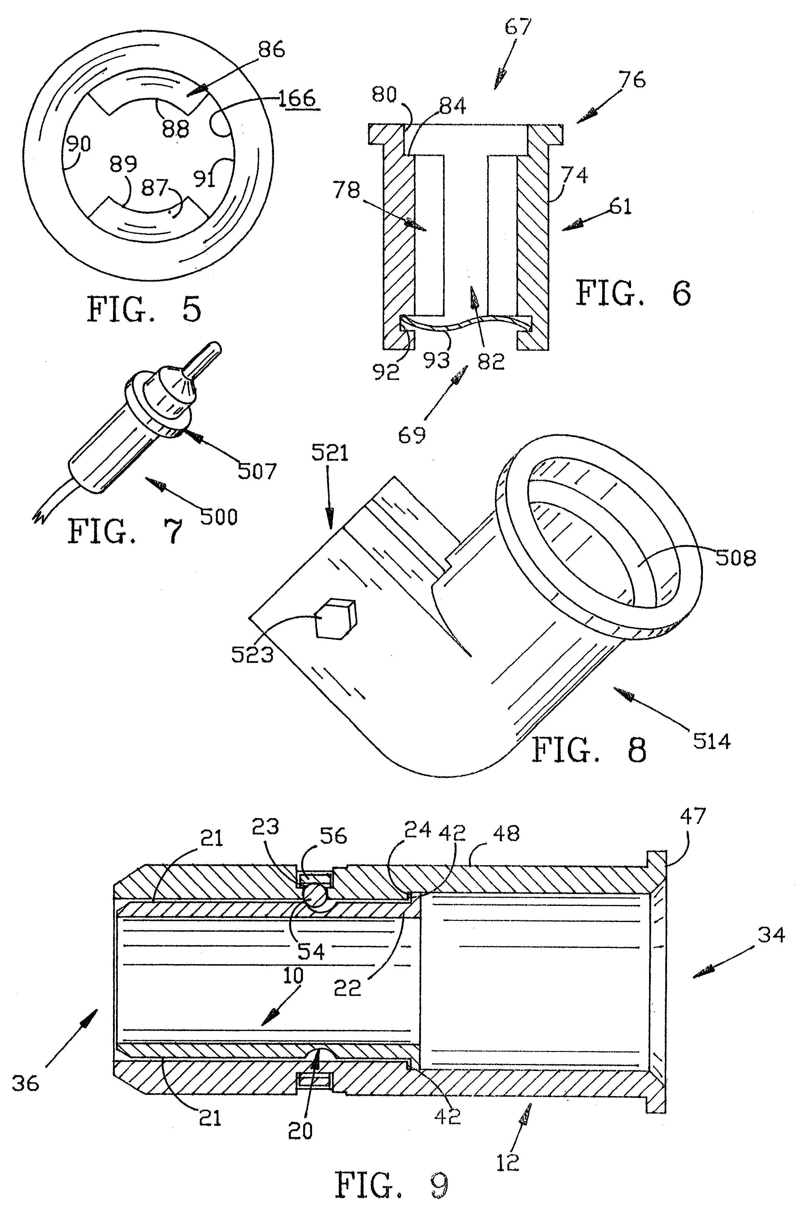
the present invention is shown in FIGS. 4-6, and 12-18, with a variation of this second embodiment shown in FIGS. 19-22. The embodiment shown in FIGS. 4-6 and 12-18 includes a back-loading sensor 60 that loads from the underside or proximal end of sensor housing 61. This differs from the front-loading sensor 10 shown in FIGS. 1-3 and 9-11.

Sensor 60 includes a proximal end 63 and a distal end 65. Similar to the sensor 10 shown in FIG. 1, the proximal end 63 of sensor 60 includes a movable plunger element 150. Sensor housing 61 also includes a proximal end 67 and a distal end 69. When the sensor 60 is engaged to the sensor housing 61, the proximal end 63 of the sensor 60 disposed adjacent to the proximal end 67 of the sensor housing 61.

The sensor 60 of the second embodiment differs in physical characteristics from the sensor 10 of the first embodiment in three important respects. First, sensor 60 has no circumferential groove, such as circumferential groove 20. Second, sensor 60 inclu...


PUM


Abstract

An improved sensor and system of attaching sensors to their associated equipment, tooling or product. This attachment device provides stability of the sensor, quick removal and installation and a definite seating position thus providing a consistent reference point. The sensor holding system combines a flange on the sensor with a groove for the engagement of pre-loaded spring biased balls, and an outer housing that incorporates an opposing flange for seating the sensor and a ring of radially inwardly biased pre-loaded balls to engage the circumferential groove in the sensors. The diameter of the outer housing is determined by the sensor body but is kept as small as practical.

Description

I. FIELD OF THE INVENTIONThe present invention relates to position sensors and more particularly to housings for position sensors for mounting the position sensor onto testing equipment or associated devices.In one embodiment, a sensor with an outer flange is used in conjunction with an outer body (sensor housing) having an inner flange to provide a definite position for the sensor, which position is repeatable on the re-installation of the original sensor or the placement of a substitute sensor into the housing. In another embodiment, the housing includes pre-loaded sprung balls that are positioned and biased to push radially inwardly against a radially outwardly facing, circumferential groove formed on the sensor to provide a radially inwardly, and axially downwardly directed force on the sensor to assure good registry to the flanges of both the sensor and outer housing, thereby maintaining a repeatable position of the sensor.II. BACKGROUND OF THE INVENTIONSensors are often placed...

Claims


Application Information

Patent Timeline
IPC IPC(8): G01B3/22G01D11/24
CPCG01B3/22G01D11/245
Inventor SARGENT, LEIGH R.
Owner APPLIED COMPOSITES
Why Eureka
Try Eureka