
Length adjustable column with axial bearing, and method of installation of the axial bearing

a technology of axial bearing and adjustable column, which is applied in the direction of seating furniture, furniture joining, bearings, etc., can solve the problems of spreader ring, production to close, and inability to re-expand to the necessary exten

Inactive Publication Date: 2002-12-17
STABILUS
View PDF19 Cites 0 Cited by
  • Summary
  • Abstract
  • Description
  • Claims
  • Application Information

AI Technical Summary

Benefits of technology

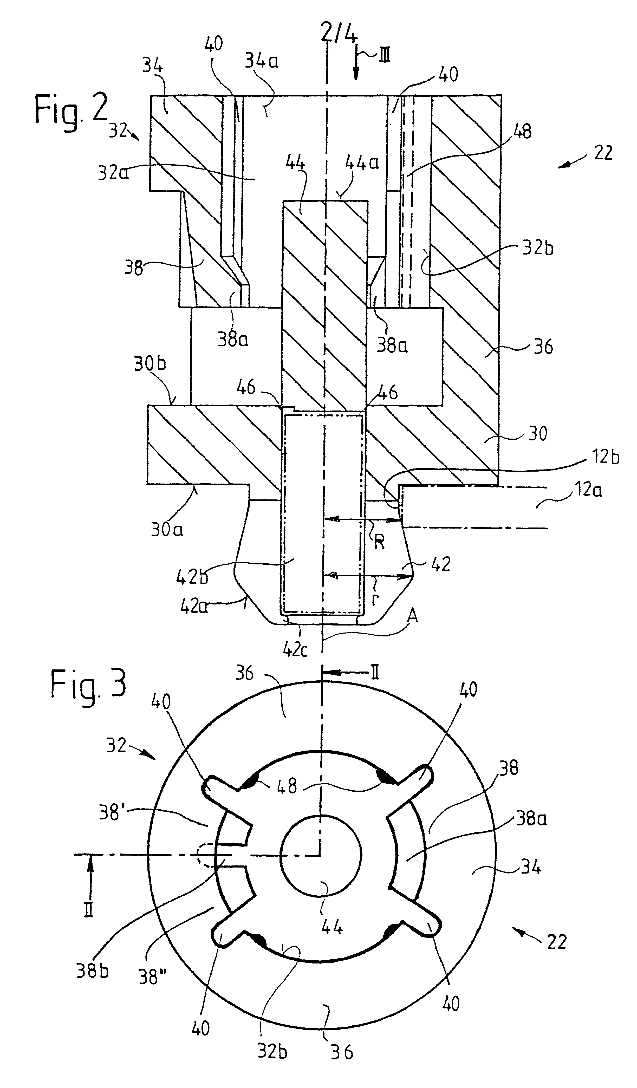
The cage may, for example, have a holding ring which is connected to a base disk of the axial bearing via at least one connecting web. At least one elongate projection extending in the axial direction can be provided on an inner surface of the holding ring and / or of the at least one connecting web. This at least one projection serves to rest on the second lengthwise end of the piston-and-cylinder unit and, because of its relatively small contact surface with the latter, prevents the occurrence of excessive frictional forces between piston-and-cylinder unit and axial bearing even when production tolerances are generous.

Problems solved by technology

A disadvantage of this embodiment is that the fixing pin and the spreader ring have to be produced to close tolerances in order to be able to ensure firm seating of the axial bearing on the base plate.
As a result of these narrow tolerances, however, it may occur during installation of the axial bearing that the spreader ring, after the introduction of the fixing pin into the base plate aperture, does not re-expand to the necessary extent because of excessive friction.

Method used


Image

  • Length adjustable column with axial bearing, and method of installation of the axial bearing
  • Length adjustable column with axial bearing, and method of installation of the axial bearing
  • Length adjustable column with axial bearing, and method of installation of the axial bearing

Examples


Embodiment Construction

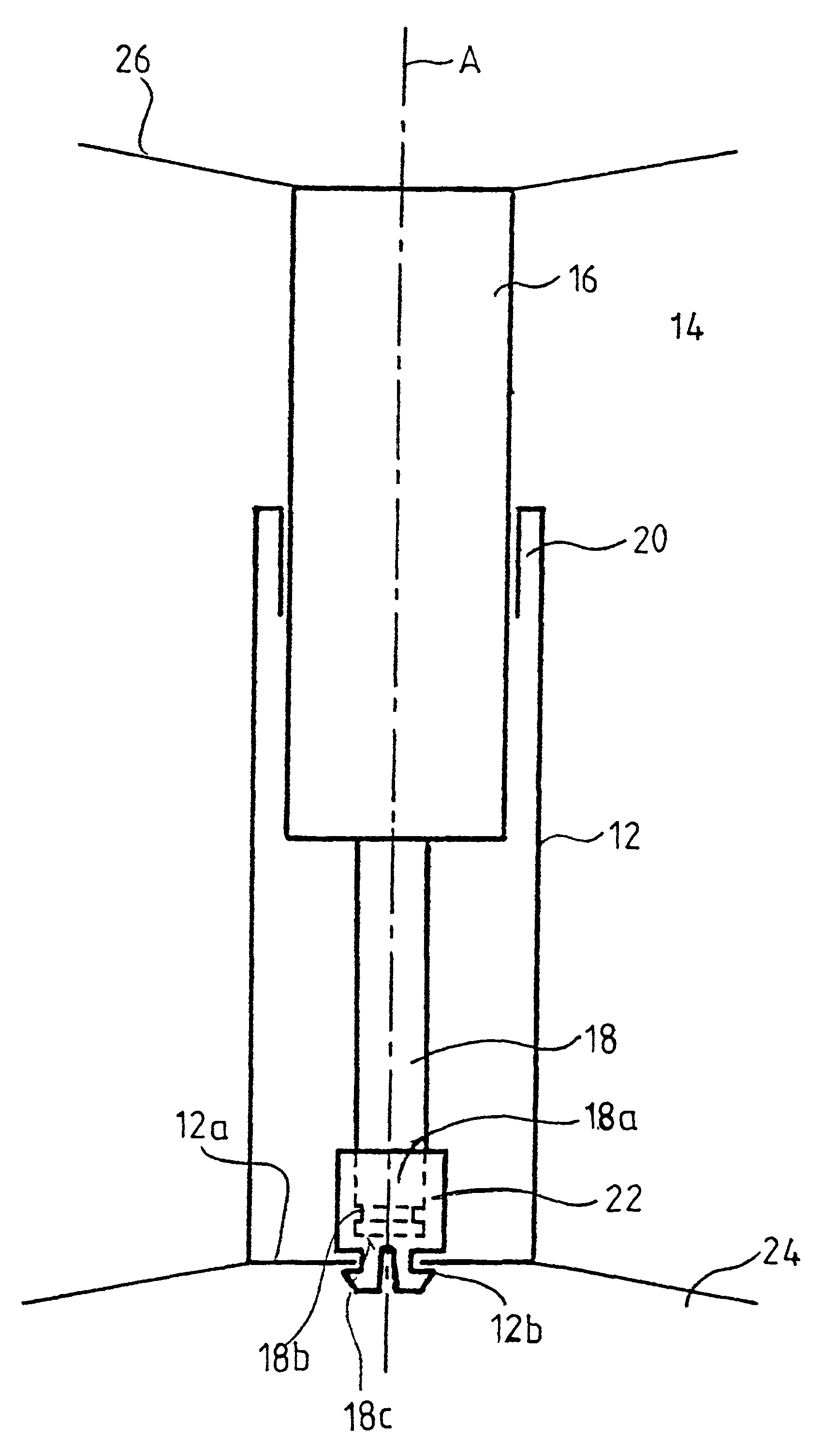
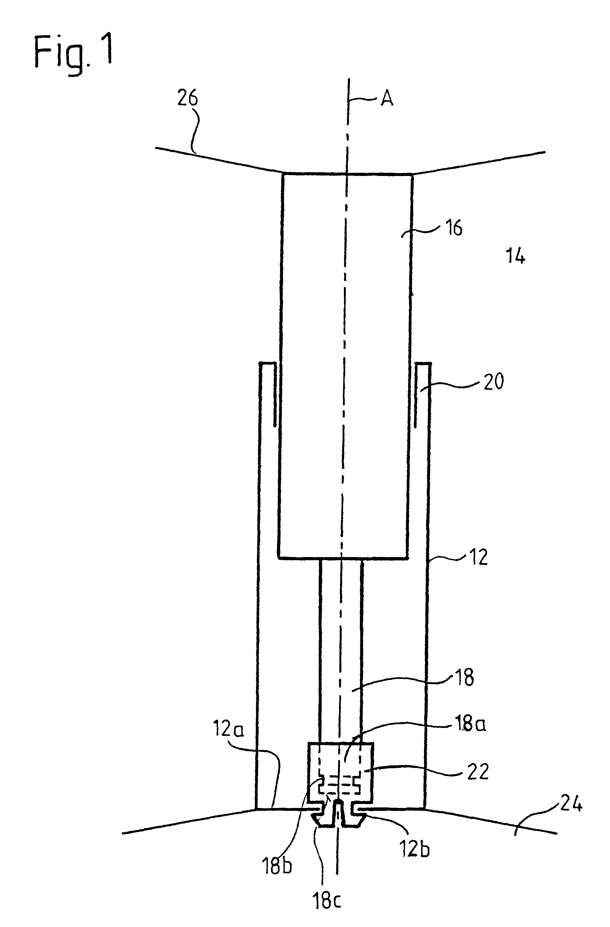
In FIG. 1, a length-adjustable column 10 includes an upright tube 12, shown roughly diagrammatically in section, and a pneumatic, hydraulic or hydropneumatic piston-and-cylinder unit 14 with a cylinder 16, a piston rod 18 and a piston connected to the piston rod 18 and guided in the cylinder 16 but not shown separately in FIG. 1. The cylinder 16 is radially supported at sleeve 20 in the upright tube 12, but guided to be axially displaceable in the direction of the longitudinal axis A. The free end 18a of the piston rod 18 is axially fixed by means of an axial bearing 22 in an aperture 12b of a base plate 12a of the upright tube 12, but is twistable relative to the upright tube 12 about its axis A.

The lower end of the length-adjustable column 10 is adjoined by a foot arrangement 24 of a chair, for example an office swivel chair. This foot arrangement 24 is merely indicated by two lines in FIG. 1. In a similar manner, a seating surface arrangement 26 of the chair adjoins the upper end...


PUM


Abstract

A length-adjustable column for chairs or the like comprises an upright tube with a longitudinal axis and a piston-and-cylinder unit radially supported and displaceably guided in the direction of the longitudinal axis. A lengthwise end of the piston-and-cylinder unit is locked by an axial bearing on a base plate of the upright tube in the axial direction. For this purpose, the axial bearing is axially fixed to the lengthwise end of the piston-and-cylinder unit. The axial bearing has at least two locking arms which lock it to the base plate of the upright tube, and a securing bolt which is pushed by the piston-and-cylinder unit between the locking arms to secure the locking.

Description

1. Field of the InventionThe invention relates to a length-adjustable column for chairs or the like, comprising an upright tube with a longitudinal axis, and a piston-and-cylinder unit received in the upright tube. A first lengthwise end of the piston-and-cylinder unit being radially supported in the upright tube and displaceably guided in the direction of the longitudinal axis, while a second lengthwise end of the piston-and-cylinder unit is locked in the axial direction by means of an axial bearing on a base plate of the upright tube having an aperture. The bearing is on the one hand fixedly connected in the axial direction to the second lengthwise end of the piston-and-cylinder unit, and on the other hand, formed with a latching arrangement which fixes the axial bearing in the axial direction on the upright tube by engagement into the aperture of its base plate.2. Description of the Related ArtThe axial bearings of such length-adjustable columns have, as indicated above, the func...

Claims


Application Information

Patent Timeline
Patent Type & Authority Patents(United States)
IPC IPC(8): A47C3/30A47C3/20A47C3/24F16B9/00F16B12/32F16C17/04F16F9/00F16F9/54
CPCA47C3/30F16M11/26
Inventor SAUER, RAINERWEBER, REINER
Owner STABILUS
Learn More