Electromagnetic actuating device and camshaft adjuster

a technology of electromagnetic actuation and camshaft, which is applied in the direction of non-mechanical valves, magnetic bodies, valve drives, etc., can solve the problems of electromagnetic actuation devices being incapable of functioning and extreme poor efficiency, and achieves low adhesion forces, small contact surface, and minimal switching time

Active Publication Date: 2015-05-05
ETO MAGNETIC GMBH
View PDF10 Cites 2 Cited by
  • Summary
  • Abstract
  • Description
  • Claims
  • Application Information

AI Technical Summary

Benefits of technology

[0011]The air gap which is preferably constructed between the permanent magnet means, preferably present as part of a disc pack, or a pole disc on the armature side, and the core body, can be set by means of the, preferably pressed in, contact element with a defined overlap over the core body to effect a force maximum (apex), i.e. the air gap can be set or respectively optimized with regard to a maximum repulsion force, whereby minimal switching times are able to be achieved.
[0012]Basically it is possible that the actuating member in the above-mentioned switching position in addition to the contact element fixed in the core body rests against the core body, i.e. that the contact surface on the core region side is formed only in sections or respectively partially by the contact element. However, an embodiment is preferred in which the contact surface on the core region side is formed exclusively by the contact element, in order on the one hand to achieve as small a contact surface as possible and hence as low adhesion forces as possible, and in order on the other hand to optimize the wear resistance of the electromagnetic actuating device, in particular the core region, as a whole. It is particularly preferred if the contact surface formed by the contact element is arranged concentrically with respect to a longitudinal centre line of the actuating member. Advantageously, the contact element projects here over the pole surface of the core body facing the permanent magnet means.
[0013]Basically, it is possible to construct the contact element from a material which offers the magnetic flux the same, or even a lower resistance, as the material of the core body. However, it is preferred, as explained in the introduction, if the magnetic conductivity of the contact element is poorer than that of the core body surrounding it, in order to bundle the field lines in a targeted manner. By means of the preferably pressed in contact element, therefore a bundling of the magnetic field lines is achieved, which brings it about that the field lines are “steered” in a more targeted manner to the oppositely directed field lines from the permanent magnet means. Therefore, an optimization of the repulsion force and hence a minimal switching time can be achieved.
[0019]It has been found to be particularly expedient if the contact surface formed by the contact element is smaller than the maximum bore diameter of the bore, i.e. in the case of the construction of the bore as a stepped bore is smaller than a front bore diameter or respectively is smaller than an external diameter of an annular axial stop surface. Particularly preferably, the contact surface formed by the contact element corresponds to a cross-sectional area of the contact element in the pressing-in region. It is especially preferred if the free end of the contact element is constructed so as to be convex—in other words, a convexity of the contact surface offered by the contact element is advantageous, because the actuating element as part of the armature assembly in the drawn-in state by a radial preferred position occurring owing to the convexity can become jammed less on the edge of the contact element.

Problems solved by technology

The invention has identified that the wear resistance can be increased by a suitable choice of material of the core region, wherein initially the problem still exists that harder core region material is generally poorly magnetically flux-conducting, which with a construction of the core body from a hardened material would lead to extremely poor efficiencies up to the point of the electromagnetic actuating device being incapable of functioning.

Method used


Image

  • Electromagnetic actuating device and camshaft adjuster
  • Electromagnetic actuating device and camshaft adjuster
  • Electromagnetic actuating device and camshaft adjuster

Examples


Embodiment Construction

[0029]In the figures, identical elements and elements with the same function are marked by the same reference numbers.

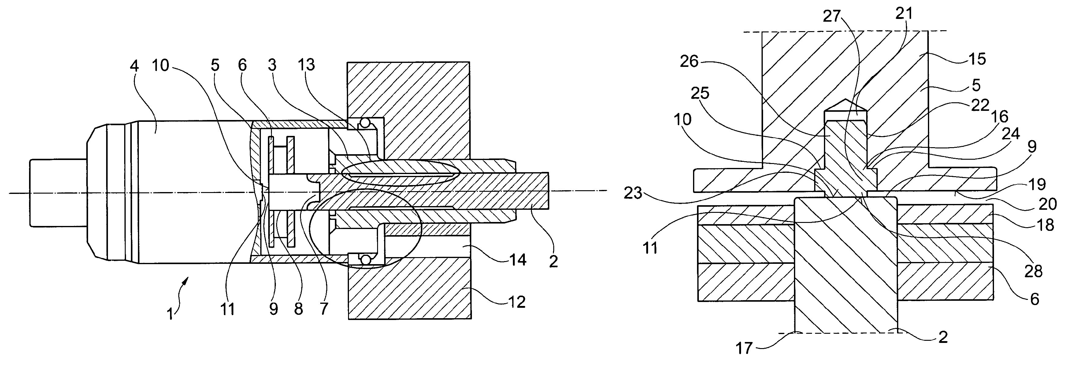
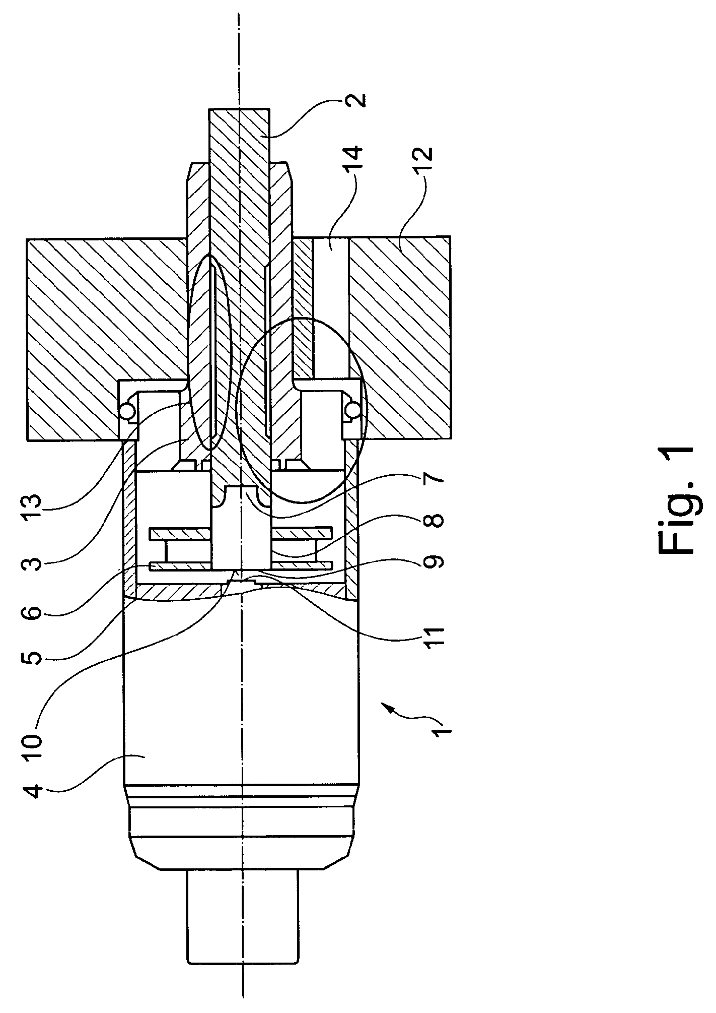
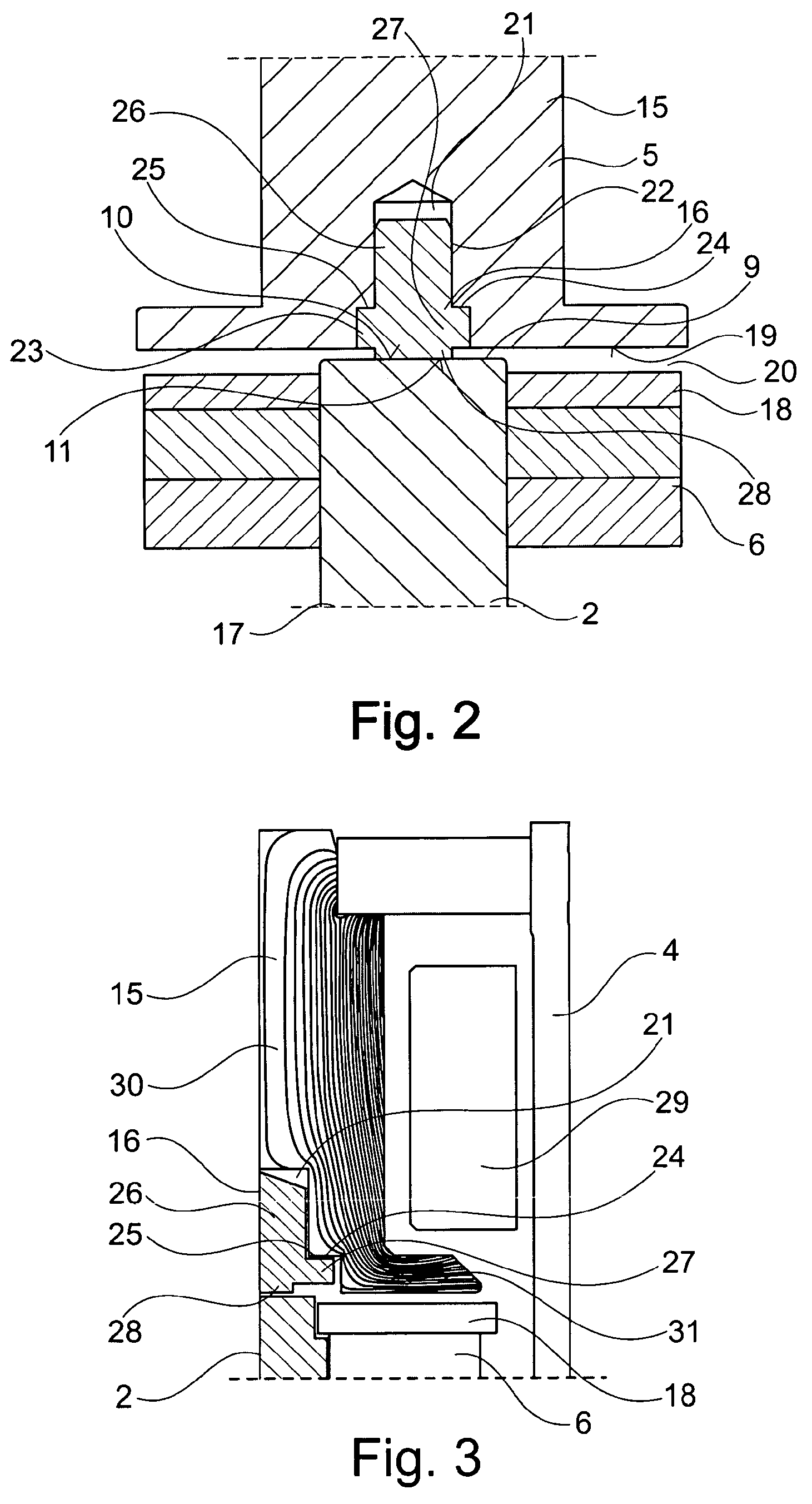
[0030]FIG. 1 shows the realization of an electromagnetic actuating device for a camshaft adjustment device which is otherwise not illustrated in further detail. A possible variant configuration of the combination of core region and armature is illustrated in FIGS. 2 and 3.

[0031]The camshaft, which is not illustrated, is actuated directly or indirectly with the aid of a continuously elongated, bolt-shaped actuating member 2, which in addition to permanent magnet means 6, which are to be further explained later, is a component part of the armature. The actuating member 2 is guided adjustably in axial direction in a sleeve-shaped bearing element 3, which undertakes at the same time the function of a magnetic yoke. The electromagnetic actuating device 1 comprises, within a cup-shaped housing 4, a coil device, known per se, not illustrated in FIG. 1, to which a magnetic c...


PUM

PropertyMeasurementUnit
temperatureaaaaaaaaaa
diameteraaaaaaaaaa
diameteraaaaaaaaaa

Abstract

The invention relates to an electromagnetic actuating device (1) for a camshaft adjustment device of an internal combustion engine of a motor vehicle, with an elongated actuating element (2) forming an engagement region on the end side and movable by the force of a coil device (29) provided in a stationary manner, which actuating element preferably has in parts a cylindrical covering contour and penetrates a cut-out (8) in permanent magnet means (6) arranged on the shell side, which are constructed for cooperating with a stationary core region (5) comprising a core body (15), and which actuating element lies in a switching position with a contact surface (11), on the end side on the actuating element side, against a contact surface (10) on the core region side. Provision is made that the contact surface (11) on the core region side is formed at least in part by a contact element (16) fixed in the core body (15), which contact element is constructed from a material which has a greater hardness than the material of the core body (15).

Description

BACKGROUND OF THE INVENTION[0001]The invention relates to an electromagnetic actuating device and a camshaft adjustment device with such an electromagnetic actuating device as actuator.[0002]In known electromagnetic actuating devices for adjusting the camshaft, the problem exists that owing to the geometry of the core region and of the armature, due to magnet technology, in the currentless state, an adhesion force acts between the core region of the actuating member of the armature. This adhesion force is intensified by the oil, situated in the adjustment unit, which collects between the contact surfaces of core region and actuating member. The adhesion force which thereby arises acts in particular in the low- and deep temperature range (+10° C. to −40° C.) negatively on the switching times of the electromagnetic adjustment unit. A lengthy idle time of the vehicle can also lead to an intensification of the adhesion force.[0003]In order to reduce the above-mentioned disadvantages, an...

Claims


Application Information

Patent Timeline
Patent Type & Authority Patents(United States)
IPC IPC(8): F01L9/04F01L1/34F01L1/46F01L13/00F01L25/08H01F7/16H01H50/54
CPCH01H50/54F01L25/08F01L1/34H01F7/1646F01L13/0036F01L1/46F01L2009/0428F01L2013/0052F01L2009/2128
Inventor GOLZ, THOMAS
Owner ETO MAGNETIC GMBH
Why Eureka
Try Eureka