Wiper device for the windows of motor vehicles

a technology for windows and motor vehicles, applied in vehicle maintenance, vehicle cleaning, domestic applications, etc., can solve problems such as restricting swiveling motion

Inactive Publication Date: 2003-03-11
ROBERT BOSCH CORP
View PDF11 Cites 57 Cited by
  • Summary
  • Abstract
  • Description
  • Claims
  • Application Information

AI Technical Summary

Problems solved by technology

Since for mounting the wiper blade on the wiper arm, the wiper arm has to be swiveled away from the window, difficulties arise if--for instan

Method used


Image

  • Wiper device for the windows of motor vehicles
  • Wiper device for the windows of motor vehicles
  • Wiper device for the windows of motor vehicles

Examples


Embodiment Construction

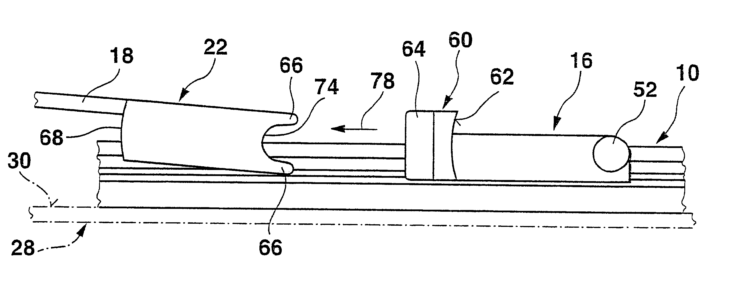
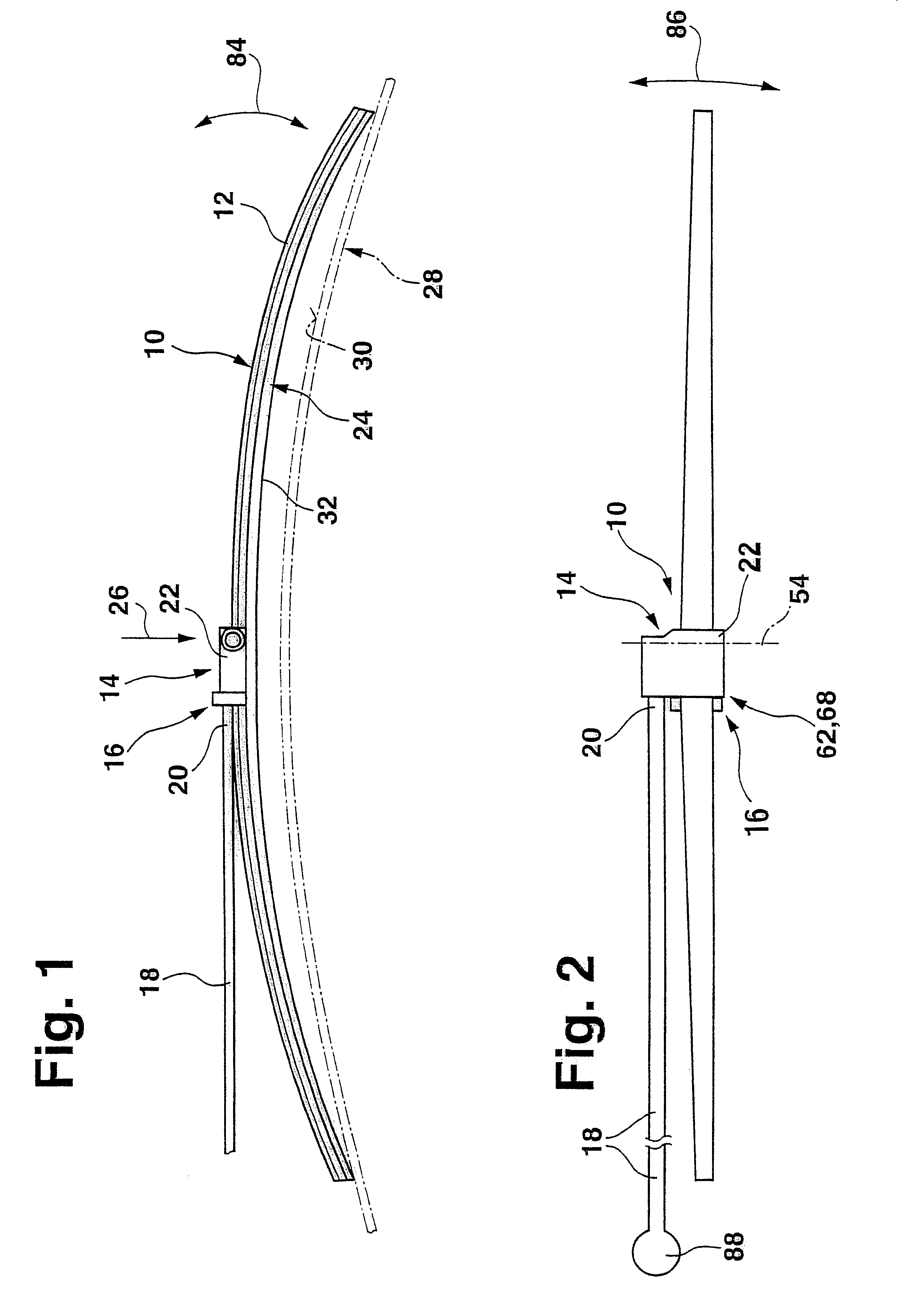
A wiper blade 10 shown in FIGS. 1 and 2 has a bandlike- elongated, spring-elastic, one- or multi-piece support element 12, on whose top, toward with the window to be wiped, there is a coupling part 16 associated with the wiper blade, which part belongs to a connection device 14 and with the aid of which the wiper blade 10 can be connected separably to a driven wiper arm 18 that is guided on the body of a motor vehicle. To that end, the wiper arm is provided on its free end 20 with a coupling piece 22 that also belongs to the connection device 14 or in other words to the wiper arm. An elongated, rubber-elastic wiper strip 24 is disposed parallel to the longitudinal axis on the underside, toward the window, of the support element 12. The wiper arm 16 and thus also the coupling piece 22 cooperating with the coupling part 16 of the wiper blade 10 are urged in the direction of the arrow 26 toward the window 28 to be wiped, whose surface to be wiped is represented in FIG. 3 by a dot-dashe...


PUM


Abstract

A wiper apparatus is proposed that is used to clean windows of motor vehicles. The wiper apparatus has a wiper arm (18), guided on the motor vehicle and driven in pendulum motion, on whose free end, remote from the pendulum shaft (88), a wiper blade (10), elongated transversely to the pendulum direction (double arrow 86) and capable of being pressed against the window (28), is separably hinged via a connection device (14) that has coupling elements (22 and 16) associated with the wiper arm and the wiper blade, respectively, wherein the pivot axis (54) extends substantially in the pendulum direction, and the wiper apparatus has at least one support shoulder (44, 46 and 68), solidly connected to the wiper arm and pointing toward the pendulum shaft (88), which shoulder is located opposite an associated interception shoulder (62), solidly connected to the wiper blade and pointing away from the pendulum shaft (88). To assure problem-free mounting of the wiper blade on the wiper arm and problem-free removal of the wiper blade from the wiper arm, even if for structural reasons the wiper arm cannot be raised in a plane that is vertical to the window, transverse to the wiping direction, at least one of the two shoulders (44, 46, 68; 62) can be moved counter to a restoring force all the way out of the opposed position relative to the other shoulder (62; 44, 46, 68).

Description

PRIOR ARTThe invention is based generally on a wiper apparatus. In a wiper apparatus of this type in the prior art (German Patent Application DE 19 75 78 72.1, as yet unpublished), the support shoulder and the interception shoulder are intended to absorb the centrifugal force that acts on the wiper blade during wiping operation, so that the hinge between the wiper blade and the wiper arm is entirely relieved relative to this force. Since for mounting the wiper blade on the wiper arm, the wiper arm has to be swiveled away from the window, difficulties arise if--for instance for the sake of vehicle body styling--the swivel joint is concealed by the vehicle body, thus blocking or restricting the swiveling motion.ADVANTAGES OF THE INVENTIONIn the wiper apparatus according to the invention, it is possible to remove the wiper blade from the wiper arm or mount it on it without performing a swiveling motion of the wiper arm beforehand, since once the shoulder or shoulders have been moved ou...

Claims


Application Information

Patent Timeline
IPC IPC(8): B60S1/38B60S1/32B60S1/40B60S1/42
CPCB60S1/38B60S1/4064B60S1/4038B60S1/3849B60S1/40
Inventor KOTLARSKI, THOMAS
Owner ROBERT BOSCH CORP
Why Eureka
Try Eureka