
Flexible trap for drains

a flexible and drain technology, applied in the field of drains, can solve the problems of unduly complex current types of "u" drains and difficult maintenance, and achieve the effect of preventing the loss of lumen patency and preventing the flattening of softened pipes

Inactive Publication Date: 2003-04-08
MANS DANIEL RUDOLF
View PDF15 Cites 6 Cited by
  • Summary
  • Abstract
  • Description
  • Claims
  • Application Information

AI Technical Summary

Benefits of technology

In a related aspect, another method for manufacture includes the steps of: taking a length of pipe, placing a restriction at one end of the pipe, passing a flow of heated air through the pipe from the other end under a slight positive pressure capable of causing distension, and when the pipe is soft and able to be distorted, wrapping it around a former of a suitable diameter and then continuing to pass now cooled gas through the pipe also under a slight distending pressure (capable of preventing loss of patency of the lumen) until the pipe is no longer soft.
Preferably the former has sides also tending to prevent flattening of the softened pipe.

Problems solved by technology

Current types of "U" trap are unduly complex, difficult to maintain because the amount of water within the trap cannot easily be ascertained, and are not adaptable to being fitted into warped positions.

Method used


Image

  • Flexible trap for drains
  • Flexible trap for drains

Examples


Embodiment Construction

The description of the invention to be provided herein is / are given purely by way of example and are not to be taken in any way as limiting the scope or extent of the invention.

DRAWINGS

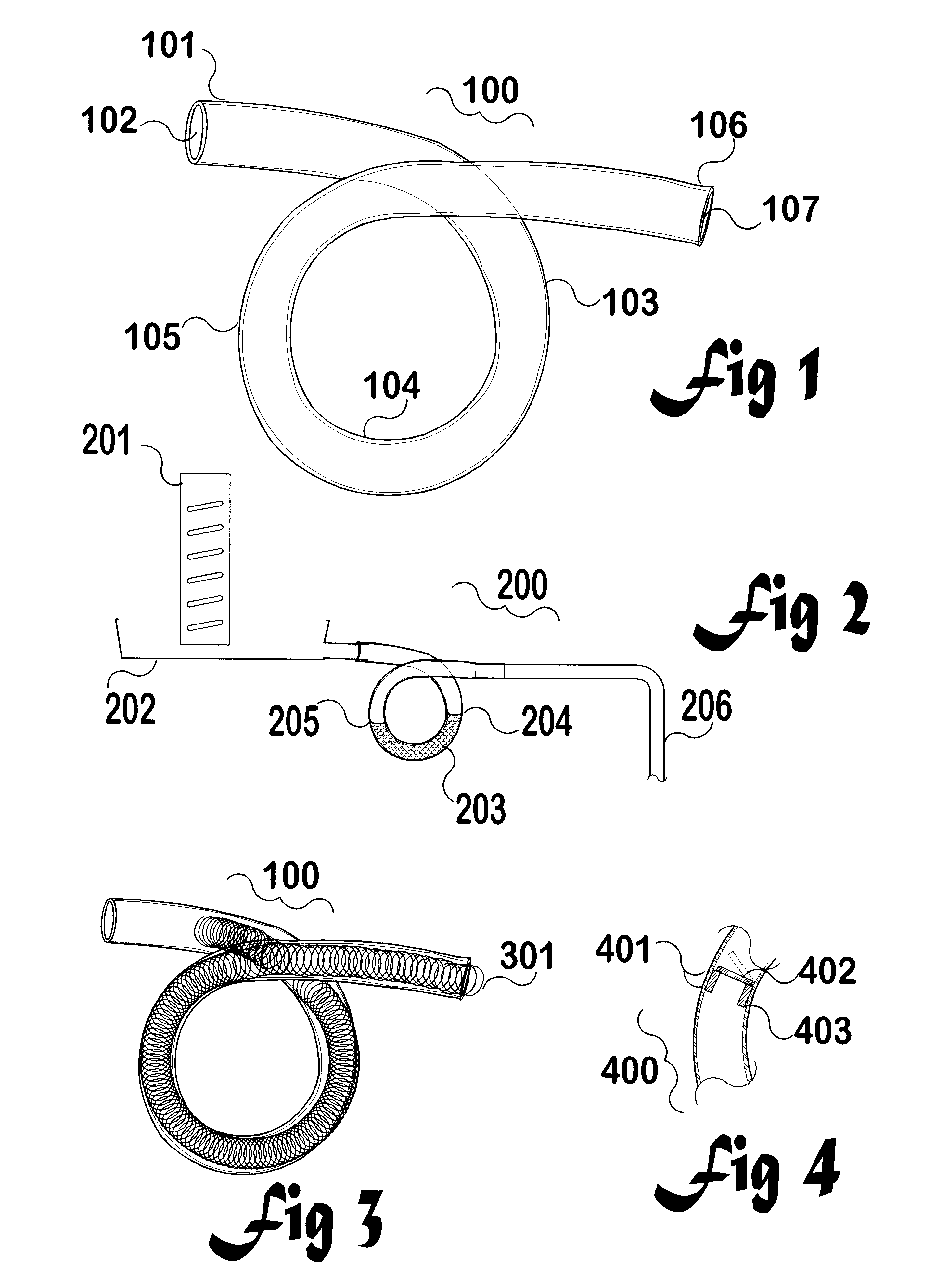
FIG. 1: shows a trap of the invention.

FIG. 2: shows how the invention is used as a trap and as a coupler in an air conditioner installation.

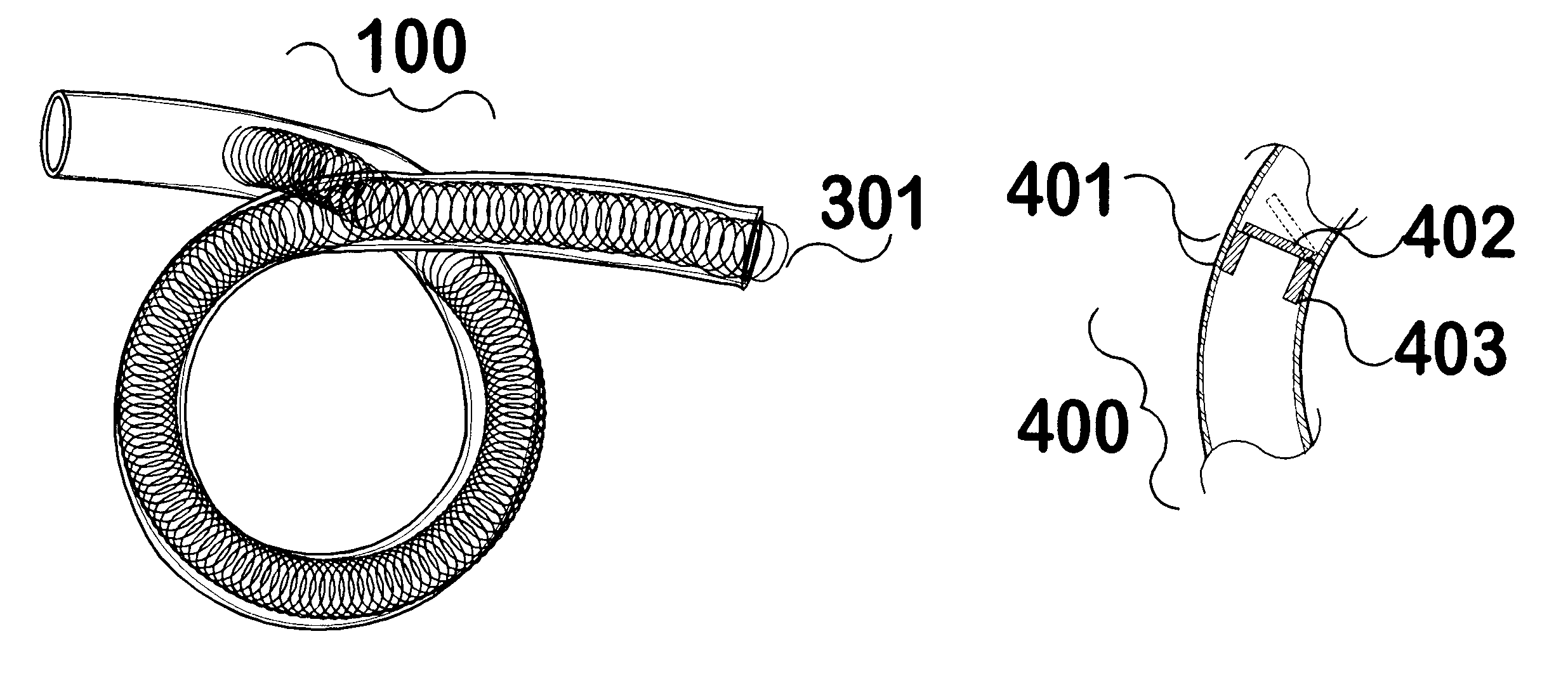
FIG. 3: shows a spring within a freshly made trap of the invention, just after being cooled while being distorted into a specified shape.

FIG. 4: shows a valve within a trap of the invention.

In general the examples described within this invention relate to traps for carrying condensate from air conditioner drip trays towards a drainage system, although it must be realised that the same devices can be adapted for use with other plumbing applications currently employing "S" or "P" type traps, and may even be usable as fluid-carrying vibration buffers where parts of an installation move in relation to other parts yet fluids must be carried between them. Indeed, the in...


PUM

PropertyMeasurementUnit
outer diameteraaaaaaaaaa
thicknessaaaaaaaaaa

Abstract

Traps particularly intended for carrying condensate from air conditioner drip trays towards a drainage system are constructed from a single turn of a flexible thermoplastic pipe; each unit being preformed when in a heat-softened state into a shape of a one-turn coil resembling the twist in a pig's tail, or the Greek "alpha" (alpha) symbol. Traps are made of a transparent flexible durable thermoplastics material, such as polyvinyl chloride, and internal contents may be inspected through the trap wall. Being flexible, the traps can reliably connect mis-aligned conduits. Being flexible, the traps can serve as reliable connectors between conduits where relative movement is a problem such as where vibration or earthquakes occur.

Description

FIELDThis invention relates to plumbing, to plumbing traps and plumbing couplers made of flexible pipe, and to plumbing traps having a shape suitable for use in conjunction with drainage of condensate from refrigeration units and in particular with air conditioning units or the like.An air conditioner employs a heat exchanger for exchanging heat with room air which exchanger is generally much colder than the room air when cooling a space during a hot day. As a motor-driven fan draws air through a filter and over the metal fins of the heat exchanger (and then into the space being conditioned) moisture in the air tends to condense and fall down into a drip tray, from where the condensate is led through a pipe into a drain on a continuously connected basis. As is usual in plumbing practice, a trap comprising a "U" shaped bent pipe and containing enough water to fill the base of the "U" is commonly employed to prevent bad smells from the drain from being drawn into the air conditioner b...

Claims


Application Information

Patent Timeline
Patent Type & Authority Patents(United States)
IPC IPC(8): E03C1/28F24F13/22F24F13/00B29C44/02B29C53/32E03C1/284F16L43/00
CPCF24F13/222E03C1/28B60H1/3233Y10T137/4463Y10T137/4493
Inventor MANS, DANIEL RUDOLF
Owner MANS DANIEL RUDOLF
Learn More