Base for electrical outlet and related method

a technology for electrical outlets and bases, applied in the direction of electrical apparatus casings/cabinets/drawers, coupling device connections, casings/cabinets/drawers, etc., can solve the problems of significant time requirements and the addition of bases and covers, so as to achieve the effect of relatively quick and/or inexpensive replacemen

Inactive Publication Date: 2003-05-06
HUBBELL INC +1
View PDF40 Cites 8 Cited by
  • Summary
  • Abstract
  • Description
  • Claims
  • Application Information

AI Technical Summary

Benefits of technology

Accordingly, an object of the present invention is to provide a base for an electrical outlet, and related method, wherein the base can be installed or replaced relatively quickly and / or inexpensively.
Another object of the present invention is to provide a base for an electrical outlet, and related method, wherein the base can be aligned relatively quickly and / or inexpensively.

Problems solved by technology

When installing or replacing such covers, and more particularly when installing or replacing the base component, a significant amount of time can be required.
The amount of time involved in installing, or replacing, such bases and covers therefore can add up rather quickly.

Method used


Image

  • Base for electrical outlet and related method
  • Base for electrical outlet and related method
  • Base for electrical outlet and related method

Examples


Embodiment Construction

Reference will now be made in detail to the presently preferred embodiments and methods of the invention as illustrated in the accompanying drawings, in which like reference characters designate like or corresponding parts throughout the drawings. It should be noted, however, that the invention in its broader aspects is not limited to the specific details, representative devices and methods, and illustrative examples shown and described in this section in connection with the preferred embodiments and methods. The invention according to its various aspects is particularly pointed out and distinctly claimed in the attached claims read in view of this specification, and appropriate equivalents.

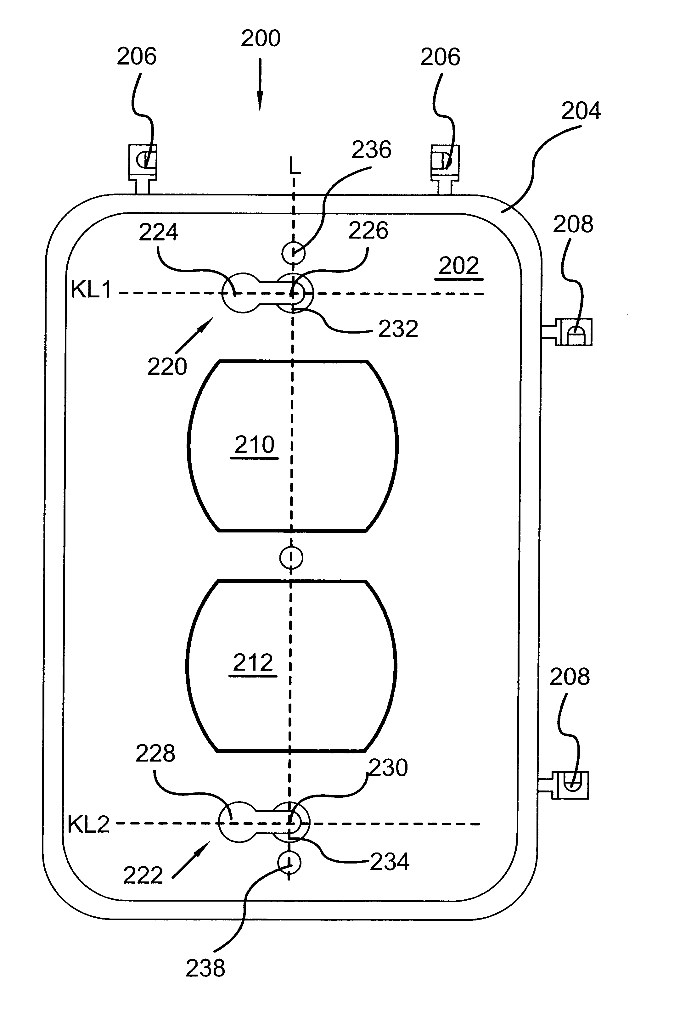
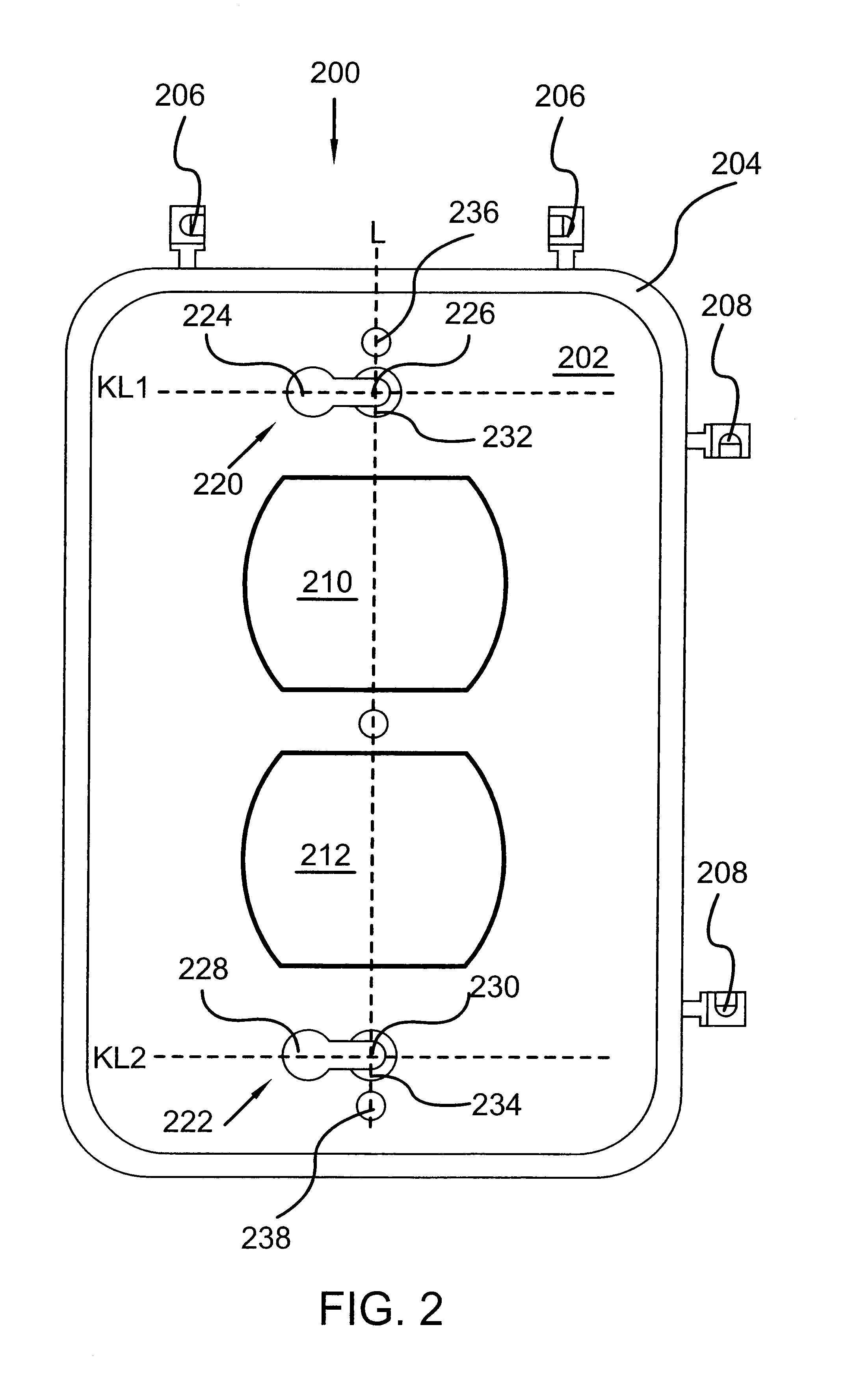
In accordance with one aspect of the invention, a base is provided for an electrical outlet. The electrical outlet includes a mounting screw aperture disposed along a longitudinal axis for receiving a mounting screw having a mounting screw head to mount the electrical outlet to a box. The mountin...


PUM


Abstract

A base for an electrical outlet. The electrical outlet includes a mounting screw aperture disposed along a longitudinal axis for receiving a mounting screw having a mounting screw head to mount the electrical outlet to a box. The mounting screw head has a mounting screw head diameter. The electrical outlet also has at least one socket face for receiving an electrical plug. The base includes a substantially planar backing member, the backing member including at least one aperture for receiving the at least one socket face. The base also includes a keyhole slot disposed in the backing member and having first and second keyhole slot apertures. The first keyhole slot aperture is larger than the mounting screw head diameter. The second keyhole slot aperture is smaller than the mounting screw head diameter and is disposed in the backing member at a location on the longitudinal axis and aligned with the mounting screw aperture when the base is mounted to the electrical outlet using the mounting screw. Related methods also are disclosed.

Description

1. Field of the InventionThe present invention relates to electrical outlets and receptacles, and more specifically, to covers for such outlets and receptacles, and related components and methods.2. Description of the Related ArtElectrical outlets traditionally have included an assembly of components that include the electrical receptacle, a box into which the receptacle is mounted, and a cover plate. The receptacle typically includes one or more sockets into which the blades of a plug, such as the plug from an electrical appliance, would be inserted. The receptacle typically is mounted to the box by a pair of box mounting screws, with one located at the top of the box and one located at the bottom. Traditional cover plates typically cover the outlet, except for the socket face or faces, at which the socket faces of the receptacle contact the plug. Such traditional cover plates commonly are mounted to the receptacle using a cover plate mounting screw located substantially in the cen...

Claims


Application Information

Patent Timeline
Patent Type & Authority Patents(United States)
IPC IPC(8): H02G3/18H02G3/12H02G3/08
CPCH02G3/18H02G3/081H02G3/121
Inventor SHOTEY, MICHAELMALTBY, EDGAR W.SHOTEY, MARCUS J.
Owner HUBBELL INC
Why Eureka
Try Eureka