Wear liner for a brush cutter

a technology for brush cutters and wear lines, which is applied in the direction of supporting devices, manufacturing tools, grain treatment, etc., can solve the problems of wear, expensive replacement of covers, and teeth to cut up brushes, and achieve the effects of convenient mounting, fast and inexpensive replacement, and extended life of covers

Active Publication Date: 2012-04-03
ALAMO GROUP
View PDF13 Cites 1 Cited by
  • Summary
  • Abstract
  • Description
  • Claims
  • Application Information

AI Technical Summary

Benefits of technology

[0006]It is the purpose of the present invention to provide a wear liner that can be easily mounted against the inner surface of the cover and quickly and inexpensively replaced when worn so as to extend the life of the cover. It is another purpose of the present invention to provide a wear liner having protective means protecting the fastening means mounting the wear liner to the cover from excessive wear.
[0008]Each hole on the inner surface of the liner is provided with raised protective means to protect the fastening means holding the liner to the cover from abrasion and wear from the sand thrown against the cover during its operation in sandy soil. The protective means can comprise a ring of hardened material welded about each hole of the liner on its inner surface. The ring is just large enough to receive within it one end of the fastening means. When fastening means comprise a nut and bolt, the opening in the ring is just large enough to receive within its confines the head of the bolt or the nut, with enough clearance to allow tightening of the connection.

Problems solved by technology

Rotation of the drum while it is being pushed against brush causes the teeth to cut up the brush.
Brush cutters are often employed in sandy conditions and the teeth on the cutters used in this environment throw a lot of sand against the cover quickly causing it to wear out.
It is expensive to replace the cover.

Method used


Image

  • Wear liner for a brush cutter
  • Wear liner for a brush cutter
  • Wear liner for a brush cutter

Examples


Embodiment Construction

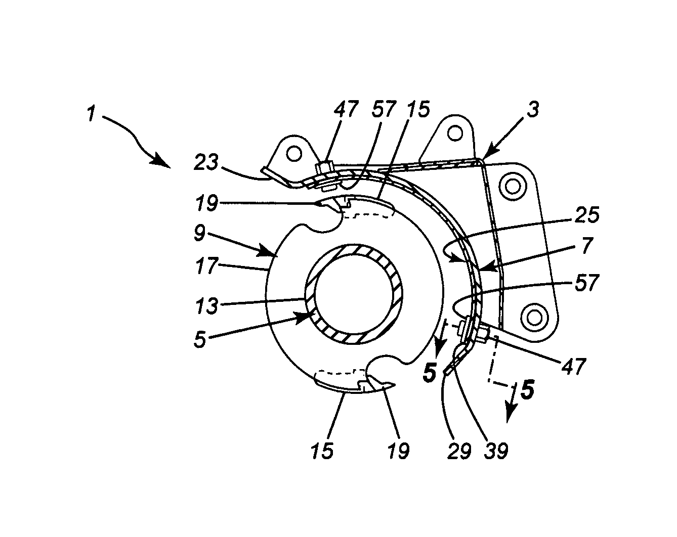
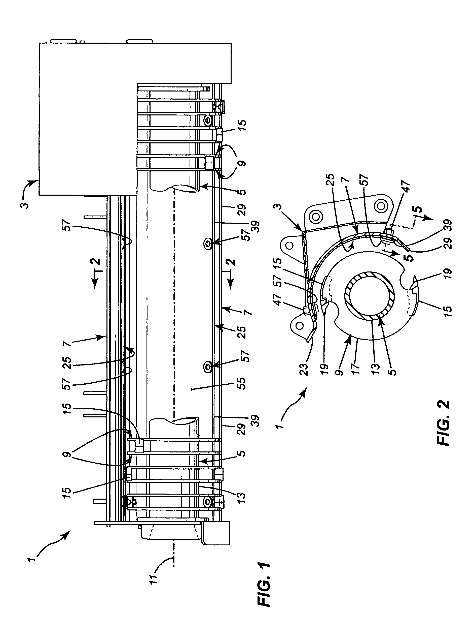
[0018]The brush cutter 1, as shown in FIGS. 1 to 3, has a cutting head 3 which comprises a cylindrical cutting drum 5 mounted within a cover 7. A plurality of annular mounting rings 9 are mounted along the length of the drum 5, the rings 9 extending transversely to the longitudinal axis 11 of the drum 5. The rings 9 are welded onto the surface 13 of the drum 5. At least one support block 15 is mounted between every pair of adjacent rings 9, the blocks 15 being welded to the rings at their outer periphery 17. A cutting tooth 19 is detachably mounted on the front of each support block 15. Rotation of the drum 5 about its longitudinal axis 11 within the cover 7 will cause the teeth 9 to cut brush when the cutting head 3 is moved against the brush. The cover 7 prevents the cut brush pieces and chips, produced from cutting the brush, from being widely dispersed.

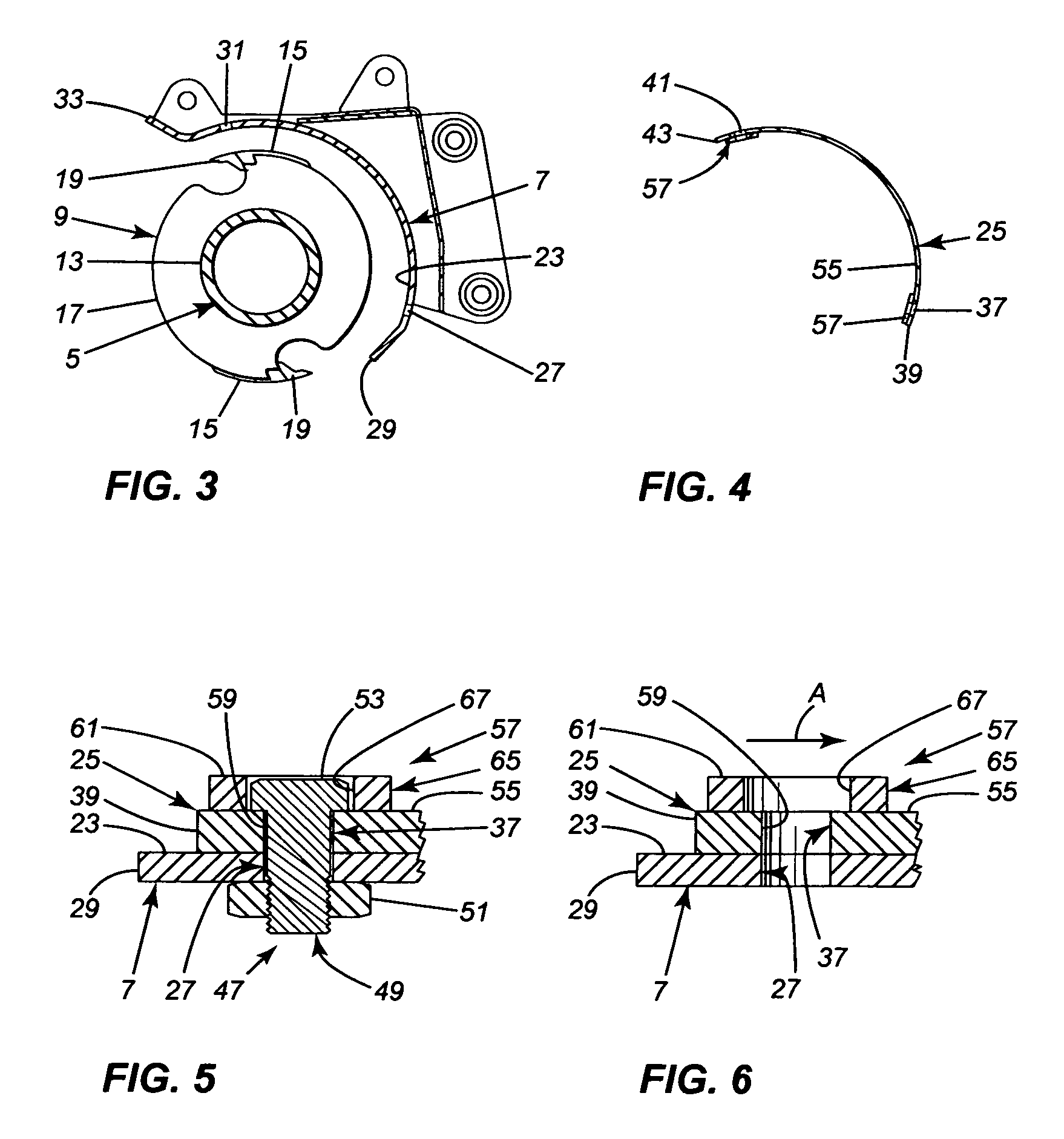
[0019]When working in sandy ground, the teeth 9 will often throw sand up against the inner surface 23 of the cover 7 causing it ...


PUM


Abstract

A wear liner for use with a brush cutter, the cutter having a cylindrical, rotatable, cutting drum carrying cutting teeth and a cover at least partially covering the drum to limit dispersal of cut material. The liner comprises a sheet of material which can be shaped to fit against the inner surface of the cover. The liner has holes on its sides for use in detachably connecting the liner with fastening means to the cover against the cover's inner surface. The liner has protective means mounted on its inner surface adjacent each hole to protect part of the fastening means located adjacent the inner surface of the liner, when the liner is mounted to the cover and the fastening means extend through the opening, from wear by material thrown by the cutter during its operation.The invention is also directed toward a brush cutter incorporating the liner.

Description

BACKGROUND OF THE INVENTION[0001]1. Technical Field[0002]This invention is directed toward a wear liner for a brush cutter and to a brush cutter incorporating the wear liner.[0003]2. Background Art[0004]Brush cutters employ a cylindrical drum with cutting teeth mounted on the drum. Rotation of the drum while it is being pushed against brush causes the teeth to cut up the brush. The drum is partly covered with a part cylindrical hood or cover to support the drum and the means rotating the drum and to limit the dispersal of the wood pieces and chips produced by the brush cutter when operated. The unit is carried on the end of a boom on a vehicle or at the front of a vehicle.[0005]Brush cutters are often employed in sandy conditions and the teeth on the cutters used in this environment throw a lot of sand against the cover quickly causing it to wear out. It is expensive to replace the cover.SUMMARY OF THE INVENTION[0006]It is the purpose of the present invention to provide a wear liner...

Claims


Application Information

Patent Timeline
Patent Type & Authority Patents(United States)
IPC IPC(8): A01D34/00B02B7/00B02B5/02B02C9/04
CPCB02C18/184B02C2210/02
Inventor DENIS, LAURENT
Owner ALAMO GROUP
Why Eureka
Try Eureka