
Single use detector for an automated external defibrillator (AED)

an automated external defibrillator and detector technology, applied in the field of single-use detectors for automated external defibrillators, can solve the problems of user hesitant to use the aed, owner unfamiliarity, etc., and achieve the effects of less chance of a fault occurring, improved reliability, and reduced ownership costs

Active Publication Date: 2022-01-25
KONINKLJIJKE PHILIPS NV
View PDF7 Cites 0 Cited by
  • Summary
  • Abstract
  • Description
  • Claims
  • Application Information

AI Technical Summary

Benefits of technology

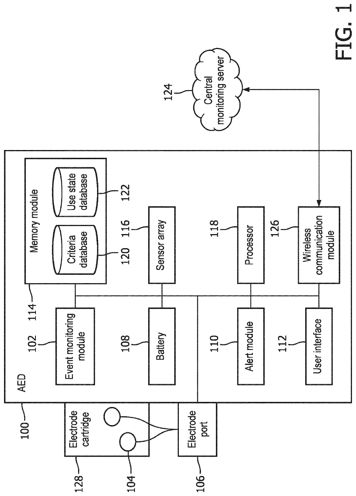
[0006]The present invention relates to systems and methods for limiting an activation of an automated external defibrillator (AED). Such a limitation appears to be counter-intuitive, but the inventors have discovered that such limiting before the battery or the pads are completely used up provides significant benefits to the customer. For example, a single use device by its nature results in improved reliability because there is less opportunity for a fault to occur. The device, after such a single use, would be returned for service or serviced in place or replaced in its entirety for the next use. In addition, a single use device may enable a lower cost of ownership because the overhead for long-term quality control of the device is replaced by quick and inexpensive refurbishment and replacement with new devices. Finally, a single use device lessens the likelihood that a customer, in an attempt to extend the life of the device, would pull the battery and so disable all further self-testing.

Problems solved by technology

One of the challenges with home-installed AEDs is that the long latency between installation and use tends to make owners unfamiliar with the operation of the AED during a rescue operation.
Although instructions are provided audibly via the speaker and graphically on the AED screen and the electrode pads, the unfamiliarity and the psychological pressure can make the user hesitate to use the AED.
In other times, the necessity of using the AED may not be clear to the user, and the user may also hesitate to use the AED due to the expense of unnecessarily changing the electrode pads and battery afterwards.

Method used


Image

  • Single use detector for an automated external defibrillator (AED)
  • Single use detector for an automated external defibrillator (AED)
  • Single use detector for an automated external defibrillator (AED)

Examples


Embodiment Construction

[0017]The following are definitions of terms as used in the various embodiments of the present invention.

[0018]The term “single use AED” as used herein refers to an AED in which after a single use, the AED will require a maintenance service to replace one or more disposable components such as battery and electrode pads or require the replacement of the AED with a new unit.

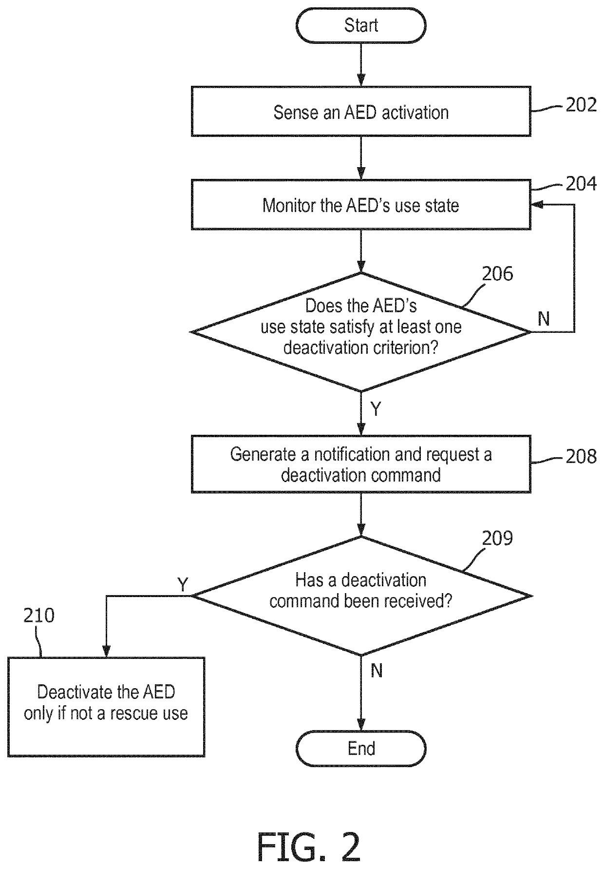
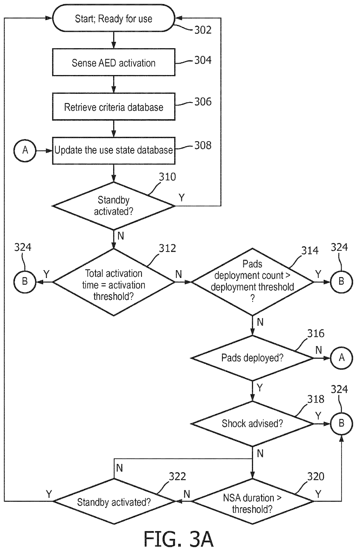
[0019]The term “use state” as used herein refers to information relating to one or more AED features or functionalities, including activation, deactivation, switching ON, switching to standby mode, electrode pad deployment, “Shock Advised” event, and “No Shock Advised” (NSA) event, among others.

[0020]The term “event monitoring module” as used herein refers to one or more hardware and software for monitoring the AED's use state. The event monitoring module includes battery monitors, timers, environment sensors, and circuitry, among others, to enable the monitoring of the AED's use state.

[0021]The term “Ready for Use...


PUM


Abstract

Systems and methods of limiting activation of a single use automated external defibrillator (AED). The method comprises using an event monitoring module to sense an activation of the AED, monitor the AED's use state, generate a notification and request a deactivation command if the AED's use state satisfies at least one deactivation criterion, and deactivating the AED when a deactivation command is received. The AED device comprises an energy source, a pair of electrodes, an alert module, a wireless communication module, and an event monitoring module.

Description

CROSS-REFERENCE TO PRIOR APPLICATIONS[0001]This application is the U.S. National Phase application under 35 U.S.C. § 371 of International Application No. PCT / EP2017 / 075722, filed on Oct. 10, 2017, which claims the benefit of U.S. Provisional Patent Application No. 62 / 407,572, filed on Oct. 13, 2016. These applications are hereby incorporated by reference herein.BACKGROUND OF THE INVENTION[0002]Cardiac arrest, ventricular fibrillation and cardiac arrhythmia are life-threatening heart conditions that require immediate cardiopulmonary resuscitation (CPR) and defibrillation to increase one's chances of survival. Defibrillation is a treatment that involves the delivery of an electric shock that allows reestablishment of the normal contraction rhythms of the heart.[0003]Over-the-counter and single use automated external defibrillators (AED) are commercially available for use in private residences and offer the advantage of providing immediate assistance during cardiac arrests at home. Sin...

Claims


Application Information

Patent Timeline
Patent Type & Authority Patents(United States)
IPC IPC(8): A61N1/39
CPCA61N1/3925A61N1/3904A61N1/3993
Inventor LANCASTER, GREGORY JAMESOCHS, DENNIS E.
Owner KONINKLJIJKE PHILIPS NV
Learn More