Blind rivet

a blind rivet and rivet head technology, applied in the field of blind rivets, can solve the problems of occupying too much space, prone to interference or damage, etc., and achieve the effects of less chance of snagging otherwise protruding rivet heads, small packaging space, and improved inner packing density of fastened components

Active Publication Date: 2012-01-17
NEWFREY
View PDF164 Cites 10 Cited by
  • Summary
  • Abstract
  • Description
  • Claims
  • Application Information

AI Technical Summary

Benefits of technology

[0004]The present invention blind rivet is advantageous over conventional blind rivets since the ends of the present invention blind rivet are flush or below flush from the outside workpiece surfaces. This achieves a smaller packaging space for improved inner packing density of fastened components with less opportunity for snagging otherwise protruding rivet heads and flanges. Furthermore, the present invention blind rivet does not employ a broken mandrel head. Therefore, assembly is less expensive and has a higher quality since the broken heads do not have to be located after setting, and the broken heads are not loose which can cause rattling and shorting of electrical circuits. Reducing setting loads are required for the pull-through mandrel versus a breakable head mandrel, thus improving the longevity of setting tools, extending times between routine maintenance and contributing to improved productivity. Moreover, the blind rivet of the present invention advantageously is set from only one side of the workpieces. The dimensional relationships and shapes of the blind rivet and mandrel are advantageous by maximizing fastening performance on a consistent basis, for example by allowing appropriate axial compression lengths and lateral expansion size hole filling of the set blind rivet in countersunk workpieces. Additional advantages and features of the present invention will become apparent from the following description and appended claims, taken in conjunction with the accompanying drawings.

Problems solved by technology

This disadvantageously takes up too much space, and is prone to interference or damage during assembly.

Method used


Image

  • Blind rivet
  • Blind rivet
  • Blind rivet

Examples


Embodiment Construction

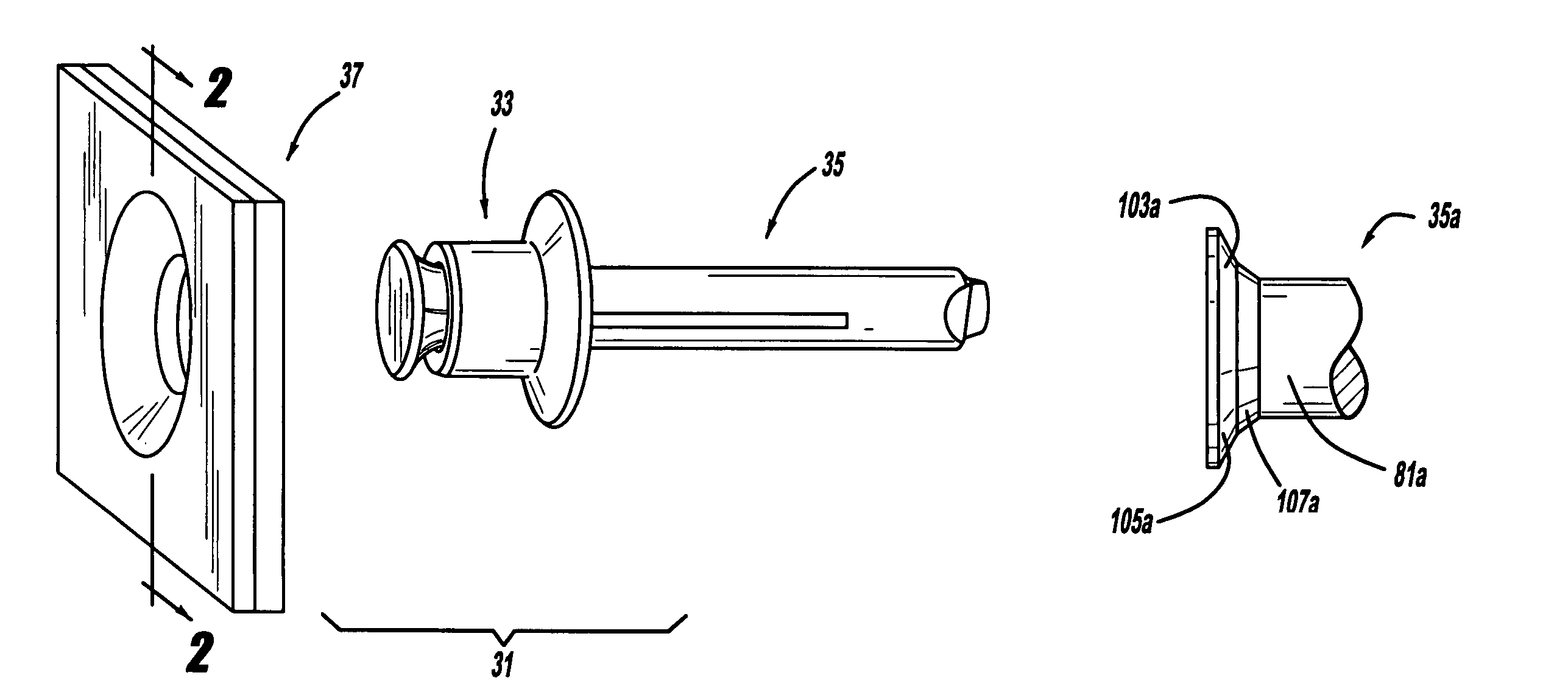
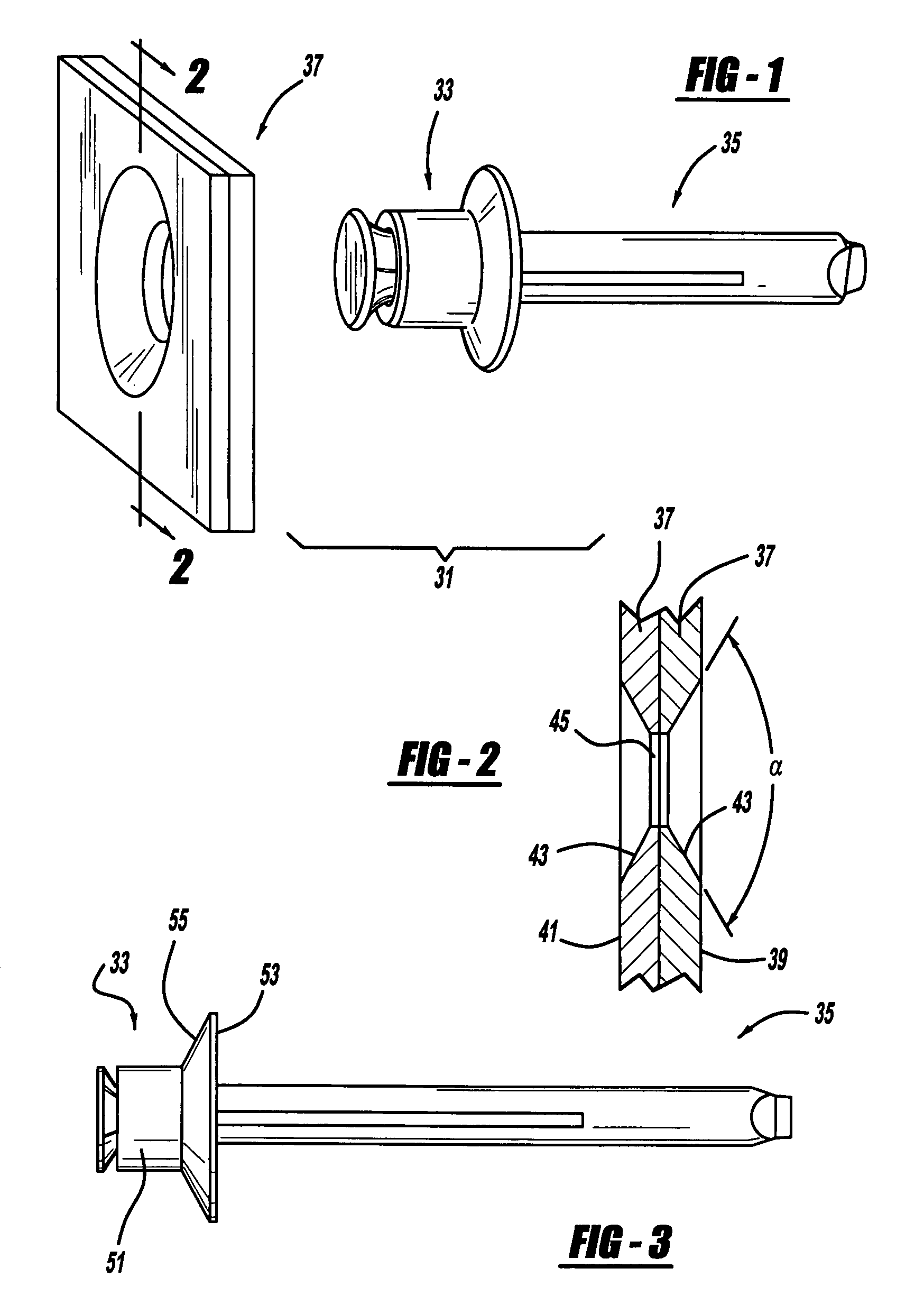
[0037]The preferred embodiment of a blind rivet assembly 31 of the present invention is shown in FIGS. 1-3. Blind rivet assembly 31 includes a blind rivet 33, a mandrel 35 and workpieces 37. Workpieces 37 are preferably component panels, boxes, cabinets or housings of electronic computer, electronic server or other such devices. Workpieces 37 include a tool-side outer surface 39 and an opposite blind-side outer surface 41 within which are countersunk depressions 43 joined by circular-cylindrical holes 45 located at the workpiece interface. Each countersink 43 has a generally frusto-conical shape with a total angle α equal to or between 120° and 90°, and more preferably between 110° and 90° total.

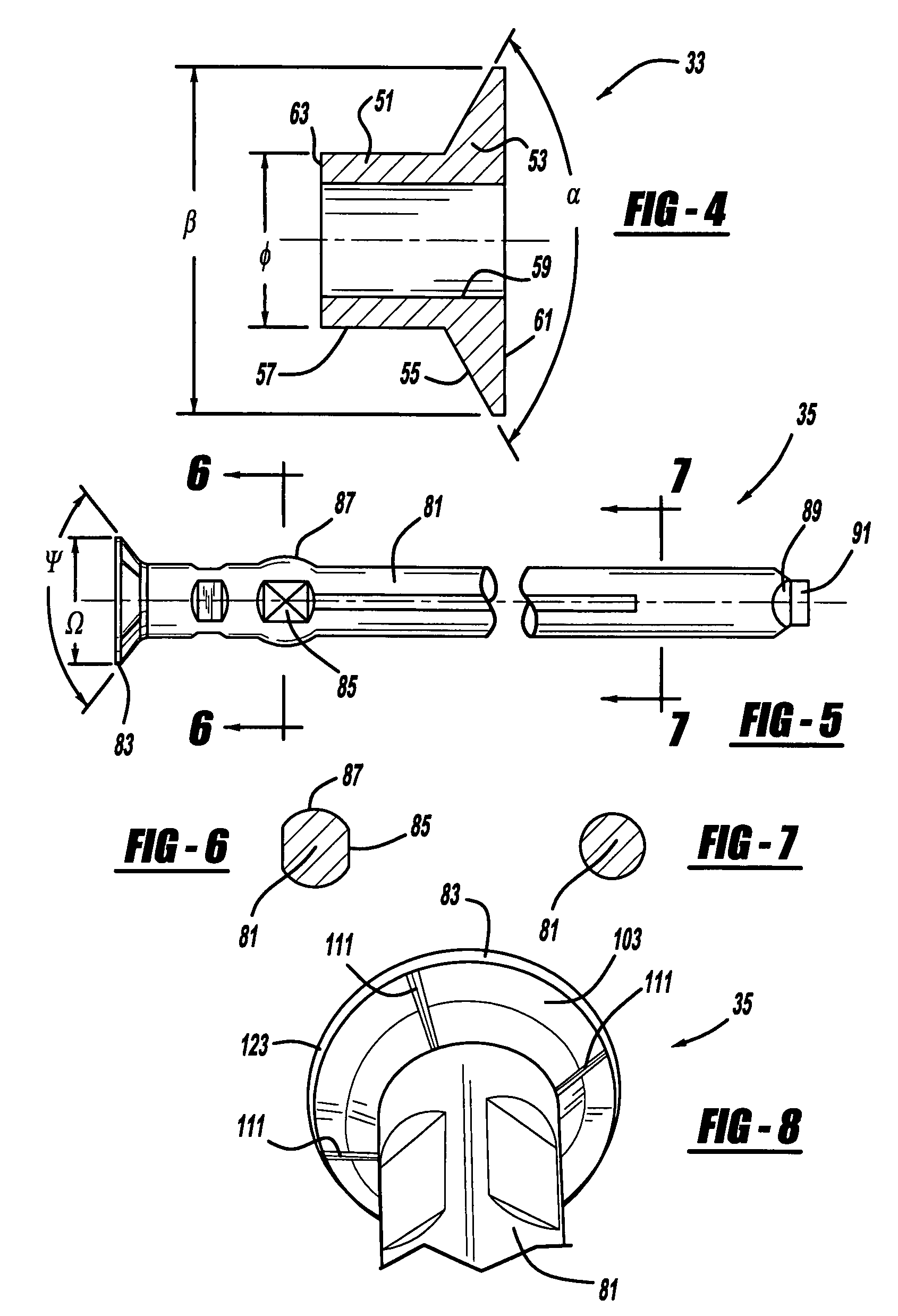
[0038]FIGS. 3 and 4 best illustrate blind rivet 33. Blind rivet 33 includes a body 51 and a tool-side flange 53. A frusto-conical outside surface 55 tapers along an outside of flange 53 and an outside surface 57 of body 51 has a circular-cylindrical shape. A through-bore 59 extends between a...


PUM


Abstract

A blind rivet assembly is provided. In another aspect of the present invention, a blind rivet has ends that are received within countersinks in one or more workpieces and a mandrel head is completely pulled through the rivet without being severed from a mandrel stem. A further aspect of the present invention includes a mandrel with one or more ribs located on an outwardly tapering shoulder.

Description

BACKGROUND[0001]The present invention generally relates to rivets and more particularly to a blind rivet assembly.[0002]It is known to set blind rivets with a mandrel. For example, reference should be made to U.S. Pat. No. 5,689,873 entitled “Tacking Fastener” which issued to Luhm on Nov. 25, 1997, Great Britain Patent No. 286,471 entitled “Improvements in and Relating to Rivets and Riveting,” and Great Britain Patent No. 2 150 661 entitled “Pull-Type Blind-Riveting Assemblies.” These rivets, however, outwardly extend past outside surfaces of workpieces after rivet setting. This disadvantageously takes up too much space, and is prone to interference or damage during assembly. More recently, flush blind rivets, using breakable mandrels, have been employed. While these constructions have significantly improved the industry, further improvements are desirable.SUMMARY[0003]In accordance with the present invention, a blind rivet assembly is provided. In another aspect of the present inve...

Claims


Application Information

Patent Timeline
Patent Type & Authority Patents(United States)
IPC IPC(8): F16B13/04
CPCF16B19/1054
Inventor DAVIES, JOHNJONES, STEVEN V.SMITH, DANIEL R.
Owner NEWFREY
Why Eureka
Try Eureka