
Magnetorheological fluid filled hinges for motion control

Inactive Publication Date: 2012-11-01
GM GLOBAL TECH OPERATIONS LLC
View PDF7 Cites 9 Cited by
  • Summary
  • Abstract
  • Description
  • Claims
  • Application Information

AI Technical Summary

Benefits of technology

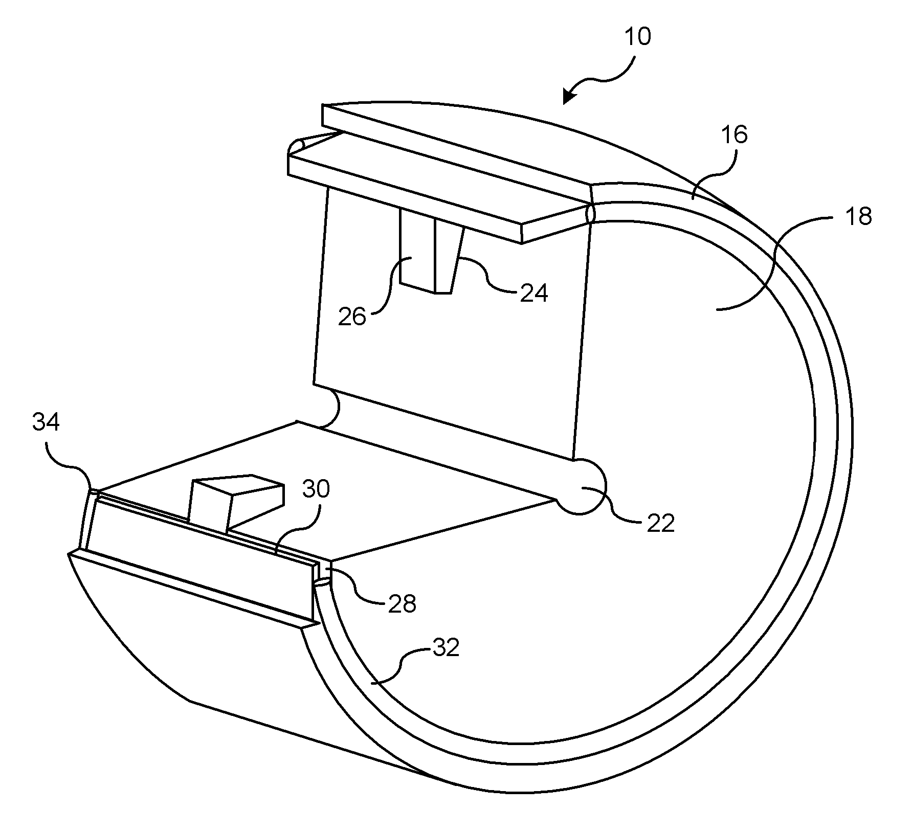
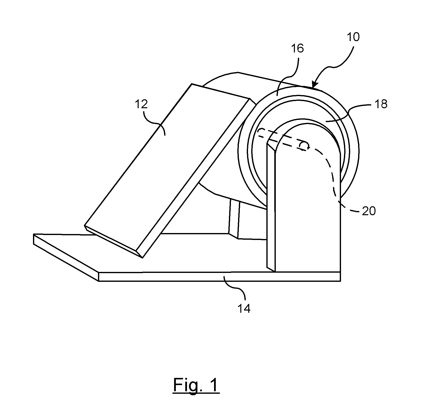
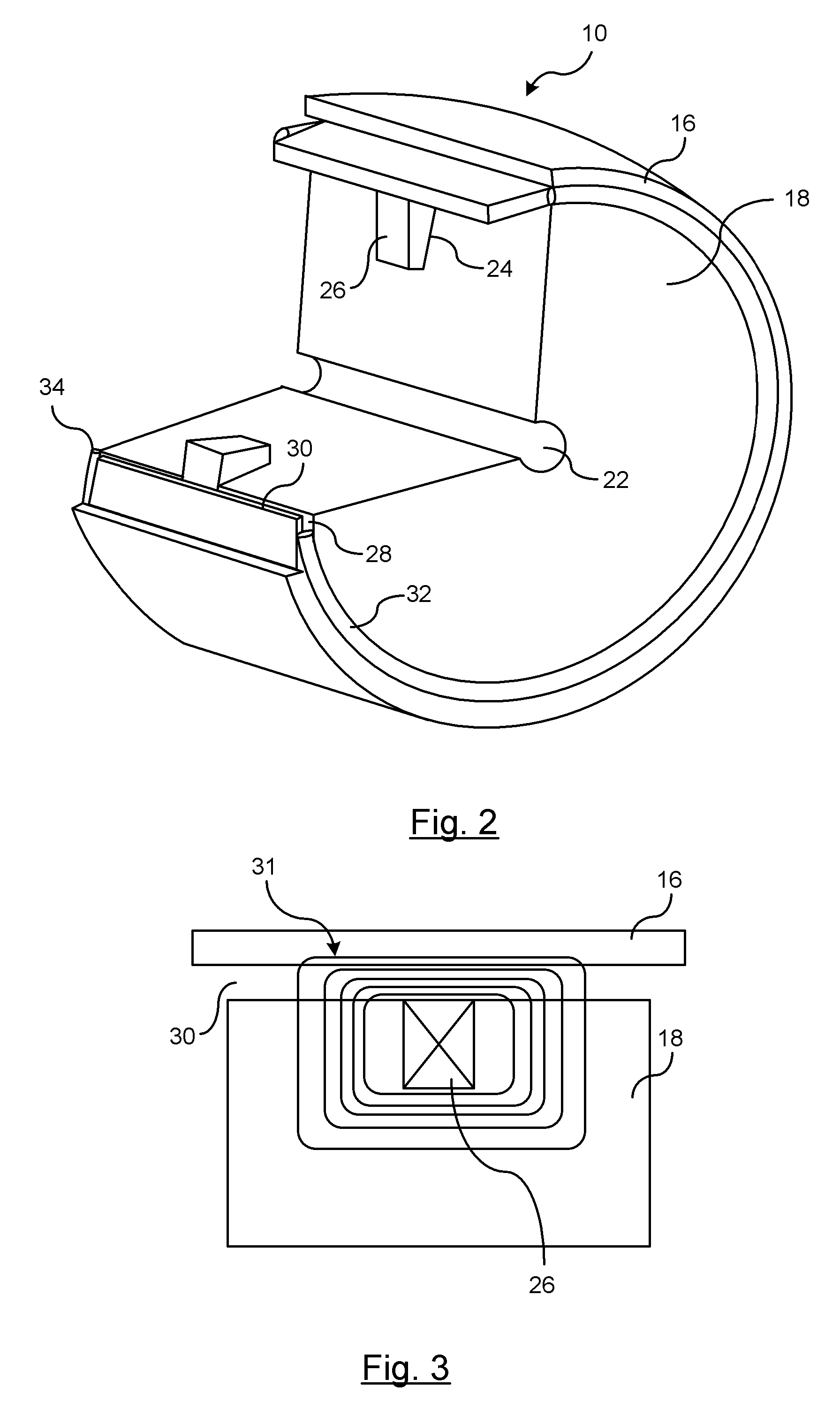
[0004]An advantage of an embodiment is controlling the movement of a hinge assembly by controlling magnetorheological (MR) fluid within an annular cavity formed between a fixed member and a pivoting member of a hinge assembly via a magnetic field exerted on the MR fluid. The magnetic field may be generated by permanent magnets, electromagnets, or a combination of both permanent magnets and electromagnets formed within the hinge assembly. The magnetic field may be variably controlled to control the speed that the hinge is able to rotate and may control the distance that the hinge assembly is pivotably displaced. This is accomplished within a relatively small package space, and allows for variable control of the hinge.

Problems solved by technology

The resistance member is typically a mechanical part that requires additional cost and packaging space.

Method used


Image

  • Magnetorheological fluid filled hinges for motion control
  • Magnetorheological fluid filled hinges for motion control
  • Magnetorheological fluid filled hinges for motion control

Examples


Embodiment Construction

[0014]There is shown in FIG. 1 a hinge assembly 10 secured to a first attachment member 12 and a second attachment member 14. It should be understood that the first attachment member 12 or the second attachment member 14 may be integrally formed as part of the hinge assembly 10 or may be secured by other methods including, but not limited to, fasteners, welding, and crimping. In FIG. 1 as shown, the second attachment member 14 may be secured to a frame whereas the first attachment member 12 may be secured to a pivotable access panel. The first attachment member 12 and the second attachment member 14 form a structure that provides access to a compartment when pivoted to an open position and denies access to the compartment when pivoted to a closed position. The access panels include, but are not limited to, a vehicle door, a tailgate of pickup truck, a trunk, an engine hood, or an interior compartment door such as a glove box. It should also be understood that the attachment members ...


PUM


Abstract

A hinge is provided for pivotably mounting a first attachment member to a second attachment member. A first member is attached to the first attachment member. A second member pivotably engages the first member and is disposed within the first member. The second member is configured for attachment to the second attachment member. An annular cavity is disposed between the first member and the second member. The annular cavity maintains a spaced relationship between the first member and the second member. A magnetorheological fluid is disposed within the annular cavity. A magnetic field generating member is configured to produce a change in a shear strength of the magnetorheological fluid within the annular cavity. The magnetorheological fluid applies a variable resistance torque between the first member and the second member for controlling a pivoting motion between the first member and the second member.

Description

BACKGROUND OF INVENTION[0001]An embodiment relates generally to hinge devices.[0002]Various moving components utilize a hinge to pivot from one position to another position. A hinge is typically a type of bearing that is secured to two moving objects and allows a respective angle of rotation between them. The two objects that are connected by the hinge rotate relative to each other about a respective fixed axis of rotation.[0003]The ability the hinge to freely rotate depends on, among other factors, the resistance built into the bearing surface of the hinge when it is manufactured. Typically, a resistance member is added to the hinge assembly that applies a resistance force to slow down or soften the opening of the two members. For example a vehicle door may have spring-like member that provides a resistance for slowing pivoting of the two components. This is typically preferred when it is undesirable to have a member pivot fast to its open or closed position where the speed of the ...

Claims


Application Information

Patent Timeline
IPC IPC(8): E05D11/10H01F7/06H01F7/02
CPCE05D11/082E05Y2201/25Y10T16/5401E05Y2900/531F16F9/535E05Y2201/254E05Y2201/46
Inventor AC, SHIVARAM
Owner GM GLOBAL TECH OPERATIONS LLC
Learn More