Distributed auxiliary power unit

a technology of auxiliary power units and power supply components, applied in the direction of machines/engines, battery/cell propulsion, vehicle energy devices, etc., can solve the problems of inability to accommodate down-sized vehicles, and achieve the effects of reducing the complexity of coupling, reducing the wear on the control unit, and reducing the wear on the modul

Active Publication Date: 2015-02-05
GE GLOBAL SOURCING LLC
View PDF3 Cites 5 Cited by
  • Summary
  • Abstract
  • Description
  • Claims
  • Application Information

AI Technical Summary

Benefits of technology

[0005]In this way, the auxiliary power unit may be configured with a plurality of modules that can be distributed throughout a rail vehicle or other vehicle, rather than packaged together in a single location. By doing so, the various modules of the auxiliary power unit may be positioned at different locations each having a smaller packaging space, facilitating the use of the auxiliary power unit even in a down-sized vehicle. Further, the location where each module is installed may be optimized for that module to reduce wear on the module and reduce complexity in the coupling between the auxiliary power unit and various components of the vehicle. For example, the control unit of the auxiliary power unit may be placed in a location that receives a relatively small amount of vibrations, reducing the wear on the control unit and reducing the packaging and extra vibration-dampening components used to keep the control unit stable. Further still, by providing a modular auxiliary power unit, each module may be selected to have a specification tailored for a particular application. For example, a first vehicle may have an auxiliary power unit with a module having a different rating (e.g., horsepower, pumping capacity, etc.) than that module in an auxiliary power unit installed in a second vehicle. Additionally, the modular nature of the auxiliary power unit may enable a module to be replaced, for example if the module is degraded or if a module of a different rating is desired, without having to replace the entire auxiliary power unit.

Problems solved by technology

However, standard APUs may comprise a large amount of packaging space in the vehicle, and such down-sized vehicles may not be able to accommodate an APU.

Method used


Image

  • Distributed auxiliary power unit
  • Distributed auxiliary power unit
  • Distributed auxiliary power unit

Examples


Embodiment Construction

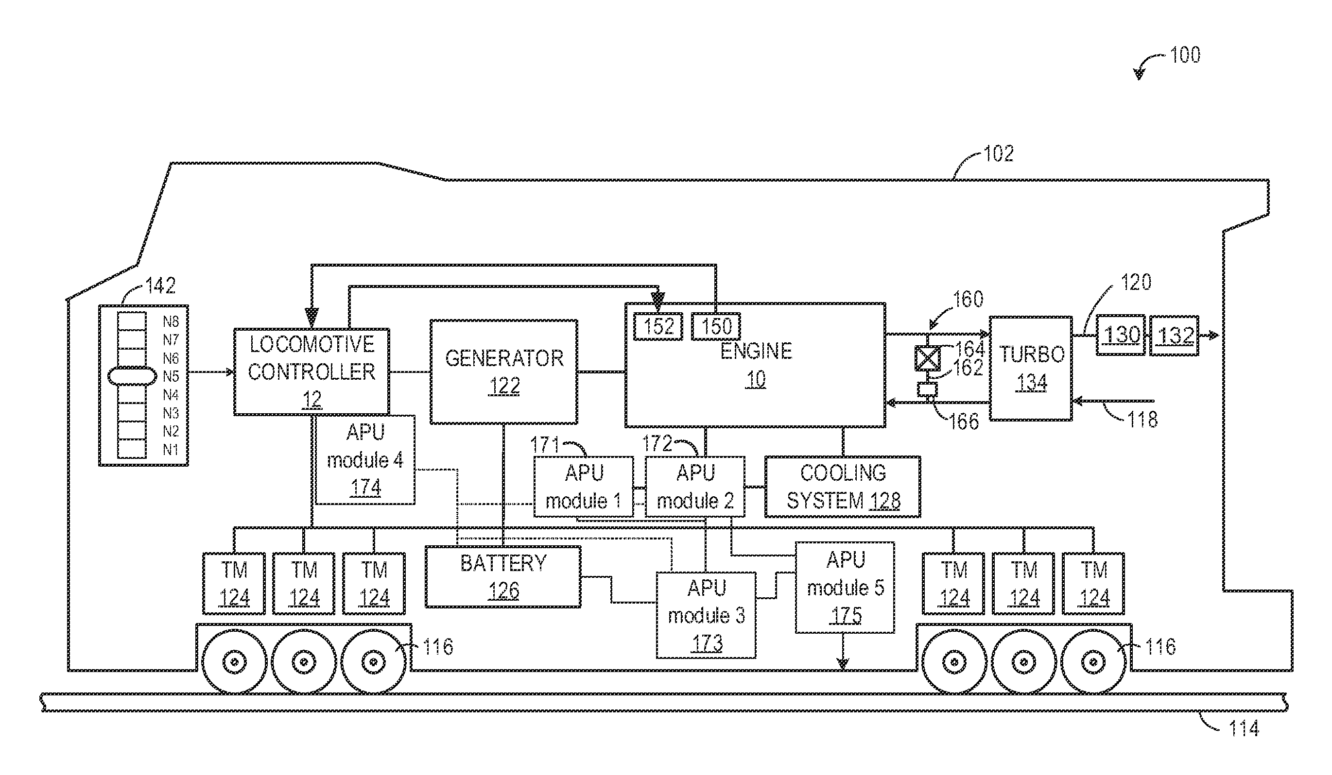
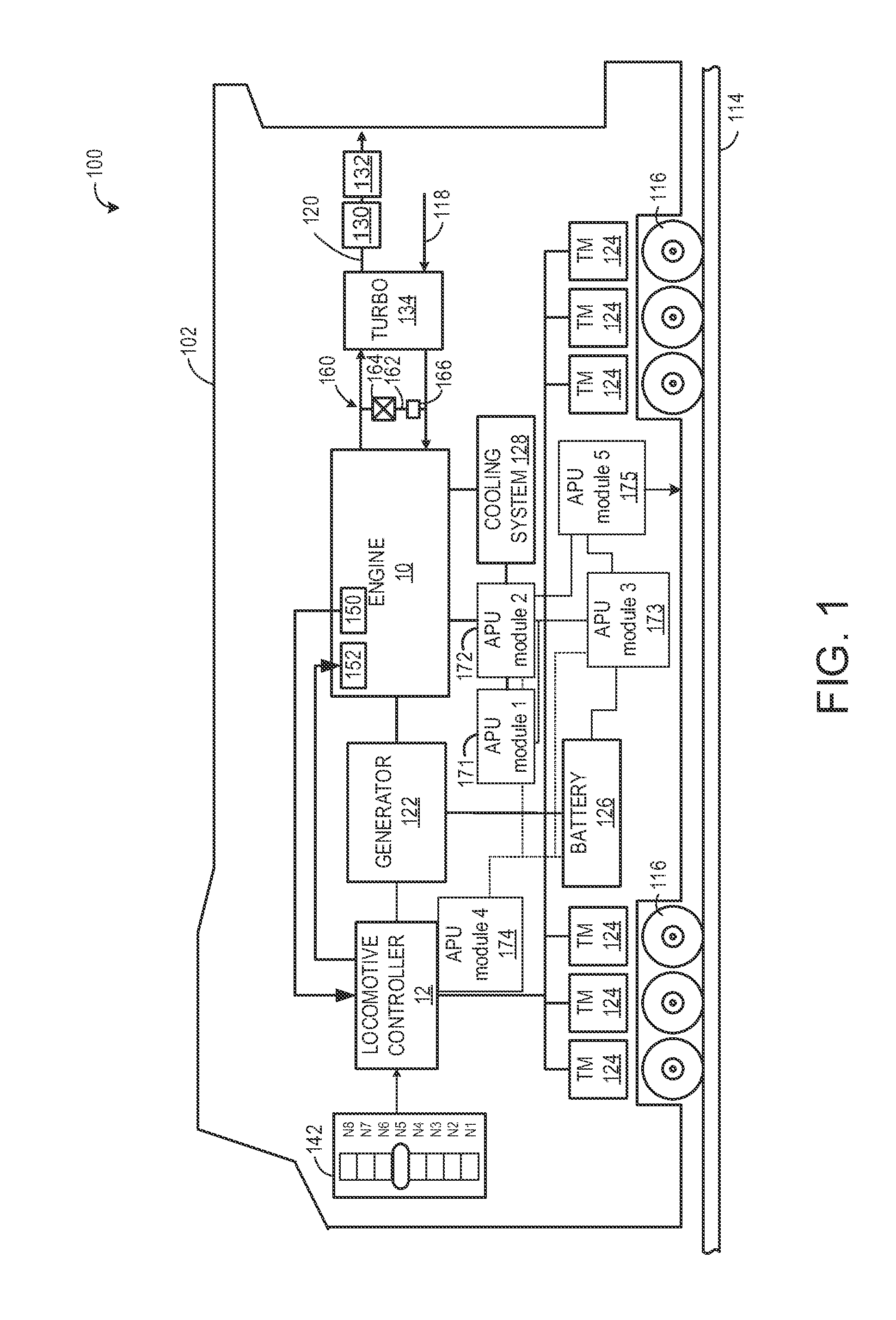
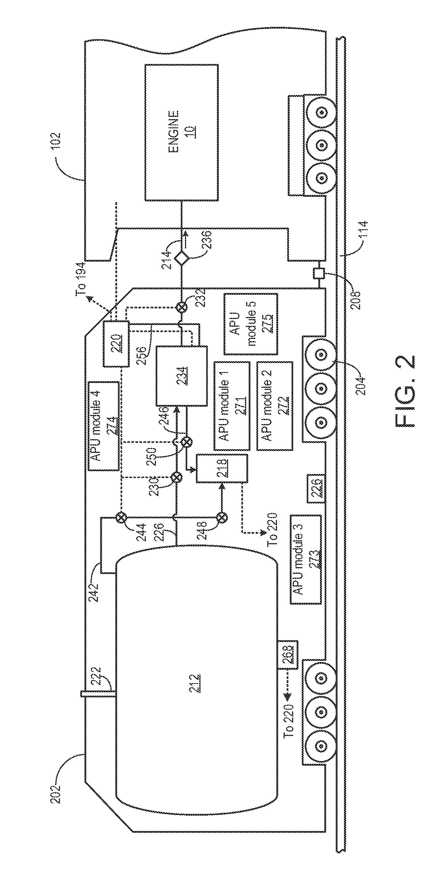
[0013]The following description relates to various embodiments of an auxiliary power unit (APU) that may provide supplementary power when a primary power-generator is inactivated. For example, the auxiliary power unit described herein may provide additional power to maintain engine coolant temperature and provide battery charge when a primary engine of a rail vehicle or other vehicle is not operating.

[0014]The approach described herein may be employed in a variety of engine types, and a variety of engine-driven systems. Some of these systems may be stationary, while others may be on semi-mobile or mobile platforms. Semi-mobile platforms may be relocated between operational periods, such as mounted on flatbed trailers. Mobile platforms include self-propelled vehicles. Such vehicles can include mining equipment, marine vessels, on-road transportation vehicles, off-highway vehicles (OHV), and locomotive or other rail vehicles. For clarity of illustration, a locomotive is provided as an...


PUM


Abstract

Various methods and systems are provided for an auxiliary power unit. In one embodiment, an auxiliary power unit comprises a plurality of independent modules configured to be installed in respective different locations within a rail vehicle or other vehicle. Each module of the plurality of independent modules is configured to carry out one or more respective functions of the auxiliary power unit for providing auxiliary power in the vehicle.

Description

RELATED APPLICATIONS[0001]This application claims priority to U.S. Provisional Application No. 61 / 861,040, filed Aug. 1, 2013, the entire contents of which is herein incorporated by reference for all purposes.FIELD[0002]Embodiments of the subject matter disclosed herein relate to an auxiliary power unit installed in a vehicle, for example.BACKGROUND[0003]Various efforts have been made to improve the fuel efficiency and emissions of vehicles. For example, an auxiliary power unit (APU) may be included in a vehicle. The APU may be activated to maintain engine coolant temperature during a non-moving condition of the vehicle. By keeping the coolant at a desired temperature via the APU, the primary engine of the vehicle may be shut down during the non-moving operation to conserve fuel. Further efforts to increase fuel efficiency and / or reduce emissions have included down-sizing of the vehicle. However, standard APUs may comprise a large amount of packaging space in the vehicle, and such d...

Claims


Application Information

Patent Timeline
Patent Type & Authority Applications(United States)
IPC IPC(8): B60L1/00F01N5/02B60L50/15
CPCF01N5/02B60L1/003B60L1/02B60L2200/26B60L2240/421B60L2240/423B60L2240/441B60L2240/443B60L2240/445B60L2240/662B60L2270/145Y02T90/16B60L50/61Y02T10/62Y02T10/70Y02T10/72
Inventor EISA, HAFIZ HASSANMELTSER, MIKECORREA, ALESSANDRO SIMOES
Owner GE GLOBAL SOURCING LLC
Why Eureka
Try Eureka