Portable environmental containment system

a containment system and environmental technology, applied in the directions of transportation and packaging, pliable tubular containers, nuclear engineering, etc., can solve the problems of toxic chemicals leaching into the ground, heavy equipment required to place and remove timber berms, and large amount of waste, so as to avoid fines and other complications, replace quickly and inexpensively, and avoid the effect of fines

Active Publication Date: 2006-03-21
STARHEIM SCOT A MR
View PDF10 Cites 11 Cited by
  • Summary
  • Abstract
  • Description
  • Claims
  • Application Information

AI Technical Summary

Benefits of technology

[0034]Sections can be removed easily to permit passage of vehicles bringing in supplies or removing equipment then easily replaced by workmen of the skill levels and tools commonly found around drilling operations. Similarly, accidentally damaged sections can be quickly and inexpensively replaced, thus avoiding fines and other complications from possible violation of environmental protection laws.

Problems solved by technology

The timber berms require heavy equipment to place and remove.
Timbers generally are too heavy to handle without machinery and if treated with creosote or other preservatives, they may leach toxic chemicals into the ground where they are placed.
Most are for special purposes, not suitable for general or arctic use.
Miss Norman's invention is intended for finished wells, and is insufficient for use as protection during the drilling operation.
The assembly cannot be disassembled without destroying at least part of the components, rendering them not reusable.
This system requires considerable labor, precision placement of the posts, and does environmental damage.
Nuts and bolts rust tight, making the Siglin dike un-repairable in the best of working conditions.
However, under arctic conditions, the normally simple chore of starting a nut on a bolt, then tightening with a pair of wrenches is a very difficult task.
Loosening and removing nuts and bolts which may be frozen in place with ice is also more difficult than expected.
Nuts and bolts and wrenches are awkward to handle with arctic gloves and are likely to be dropped, leaving a litter.

Method used


Image

  • Portable environmental containment system
  • Portable environmental containment system
  • Portable environmental containment system

Examples


Embodiment Construction

):

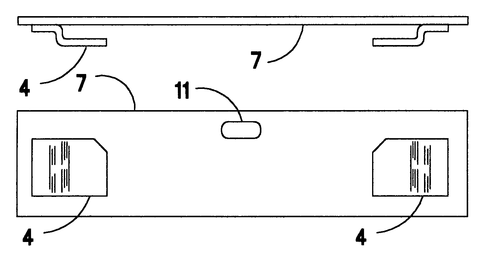
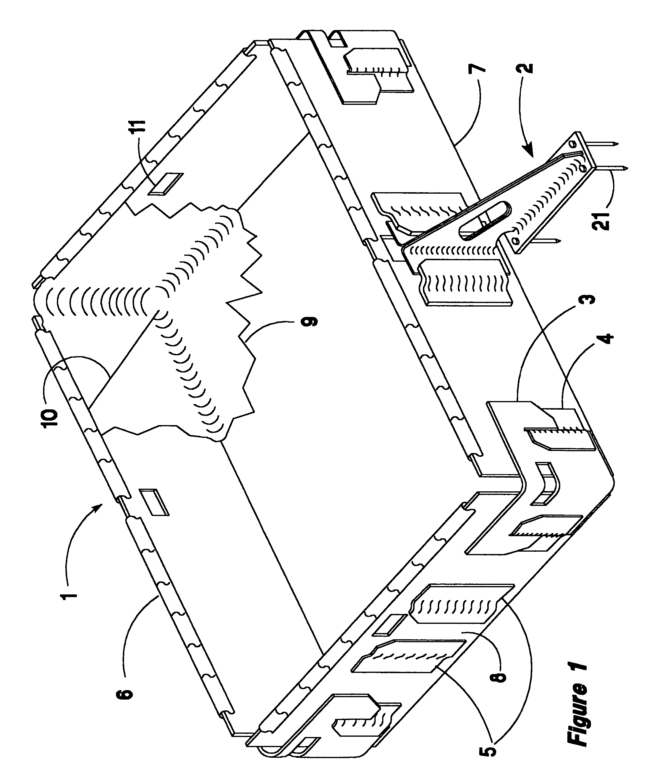
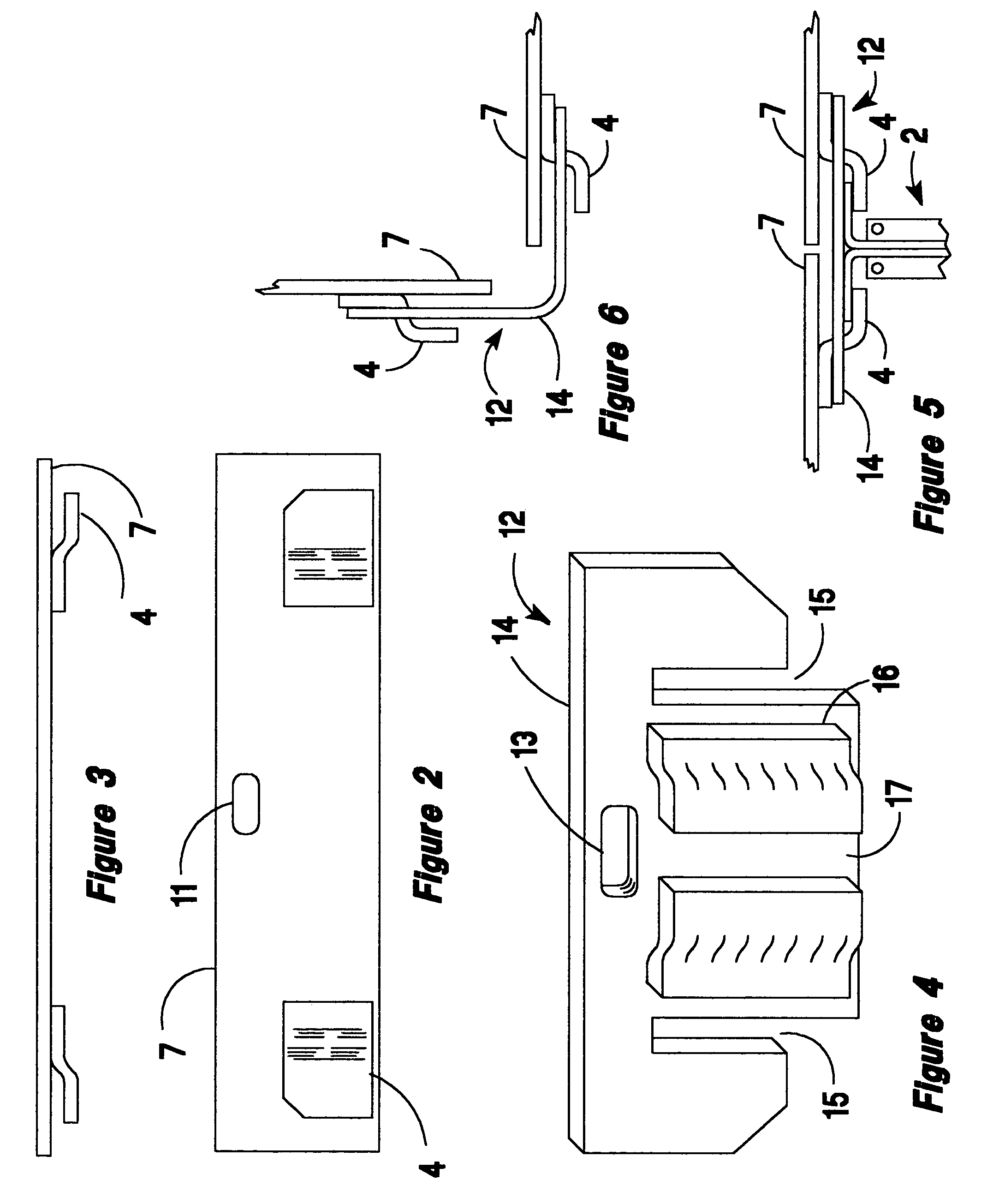
[0147]FIG. 1 illustrates an assembled embodiment of the present invention, 1. The components illustrated are the berm wall panels 7, a support gusset bracket 2, corner clips 3, panel joining hooks 4, and the bracket mounting hooks 5, which form a T slot 8 into which the support bracket 2 is inserted, liner retaining spring clamps 6, spikes 21, and the liner 9.

[0148]FIGS. 2 and 3 are orthographic views of a typical panel. The panel has joining hooks, 4, at each end comprising jogged plates welded, bolted, or riveted to the panel. The end hooks slidably engage slots in cooperating joining clips to connect adjacent panels into longer runs or to form corners. Clips on the interior portions of the panels accept gusset brackets which serve as footing to prevent the panels from sinking into the ground and resist overturning. The brackets 2 have holes through which securing spikes are driven into the ground, warehouse floor, or other surface to prevent bracket sliding and panel bowing.

[01...


PUM


Abstract

A temporary berm or bin system, easily transported, erected without tools, and easily dismantled. A set of panels or planks is joined with sliding clips to form a bin having vertical or near vertical sides. The bin is lined with an impervious sheet of geocloth to form a containment berm for use in controlling the dispersal of hazardous material spilled from storage or work facilities. Spring loaded clamps hold the geocloth securely to the uppermost plank without nailing, sewing, or other labor consuming and/or tear prone methods. The berm is particularly suited to protect oil well drilling sites in environmentally sensitive environments such as arctic tundra. No excavation or other disturbance of the soil is required to erect the protective berm. The berm is secured to the ground by spiking through triangular support gussets. In the arctic, securing may be accomplished by freezing ice or mud as an “ice mortar” over the gusset feet and along the lower edge of the planking. The berm system may be transported by ordinary truck, specially adapted transport/laying truck, or on a portable drilling platform.

Description

RELATED APPLICATIONS[0001]The present application claims benefit of filing date of Provisional Application No. 60 / 426,128 titled Portable Environmental Containment System, filed on Nov. 13, 2002, now abandoned.[0002]The present application describes additional embodiments for the containment system described in U.S. Pat. No. 6,315,495. U.S. Pat. No. 6,315,495 is incorporated by reference.BACKGROUND OF THE INVENTION[0003]1. Field of Invention[0004]This invention pertains to temporary structures serving as retaining berms or bins for holding hazardous material against escaping. In particular, to prevent oil well drilling mud and other fluids released during drilling operations from escaping the site, and to protect the environment near the tank batteries used for holding drilling fluids, fuel, and supplies. The system may be stored and transported as part of a drilling rig.[0005]2. Description of Prior Art[0006]In environments where the soil may be disturbed, earth is piled up in berm...

Claims


Application Information

Patent Timeline
Patent Type & Authority Patents(United States)
IPC IPC(8): E02B7/00E02D27/01E02D27/35E02D27/38E02D31/00E21B21/01
CPCE02D27/01E02D27/35E21B21/01E02D31/00E02D27/38
Inventor STARHEIM, SCOT A.ROSS, BRUCE D.
Owner STARHEIM SCOT A MR
Why Eureka
Try Eureka