Truss table apparatus with automatic truss movement assembly and method

a technology of automatic truss movement and assembly, which is applied in the direction of workpiece holders, manufacturing tools, other domestic objects, etc., can solve the problems of negative actuation, inadequate adjustability of prior machines, and relatively slow operation of prior machines

Inactive Publication Date: 2003-05-13
ILLINOIS TOOL WORKS INC
View PDF54 Cites 30 Cited by
  • Summary
  • Abstract
  • Description
  • Claims
  • Application Information

AI Technical Summary

Problems solved by technology

The clamping methods utilized by the prior machines have been found inadequate in terms of adjustability, positive actuation and the like.
In addition, the prior machines have been relatively slow in operation because movement of the trusses on the table during fabrication has been done primarily manually.

Method used


Image

  • Truss table apparatus with automatic truss movement assembly and method
  • Truss table apparatus with automatic truss movement assembly and method
  • Truss table apparatus with automatic truss movement assembly and method

Examples


Embodiment Construction

The invention is herein described with reference to the accompanying drawings and is not intended to limit the scope of the claimed invention, but is intended to describe particular embodiments to disclose the best mode of the invention to those skilled in the art.

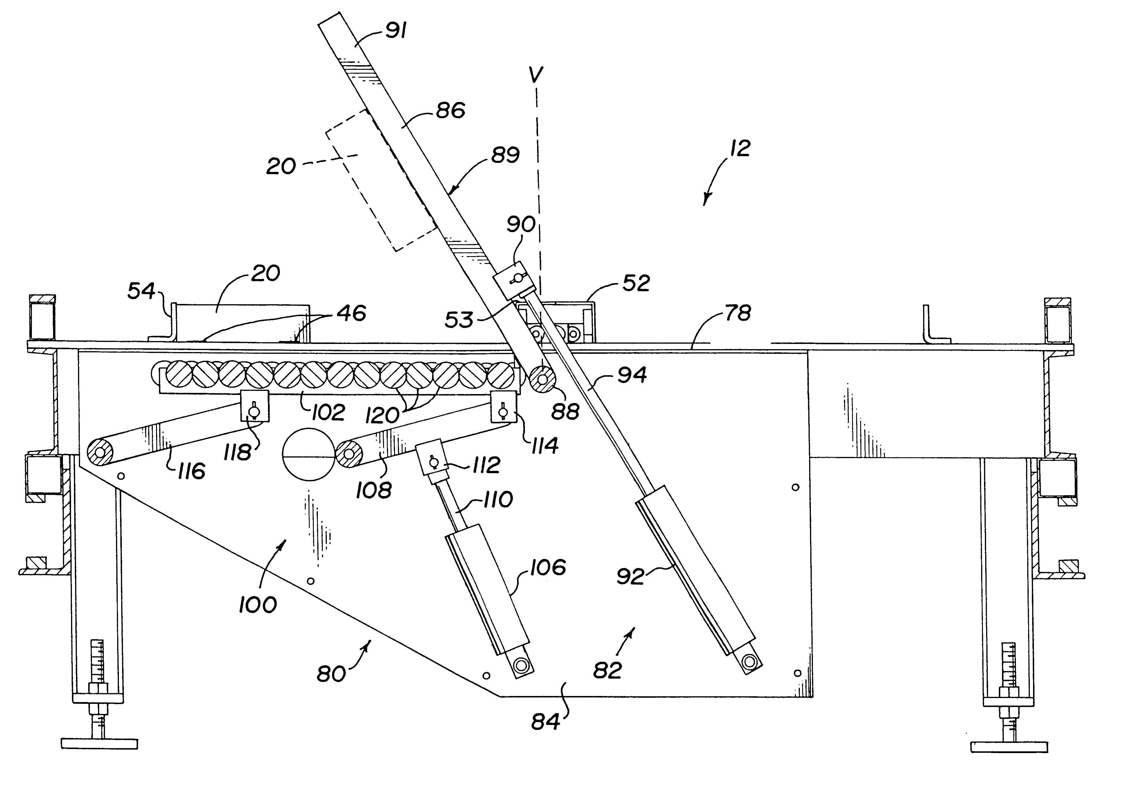
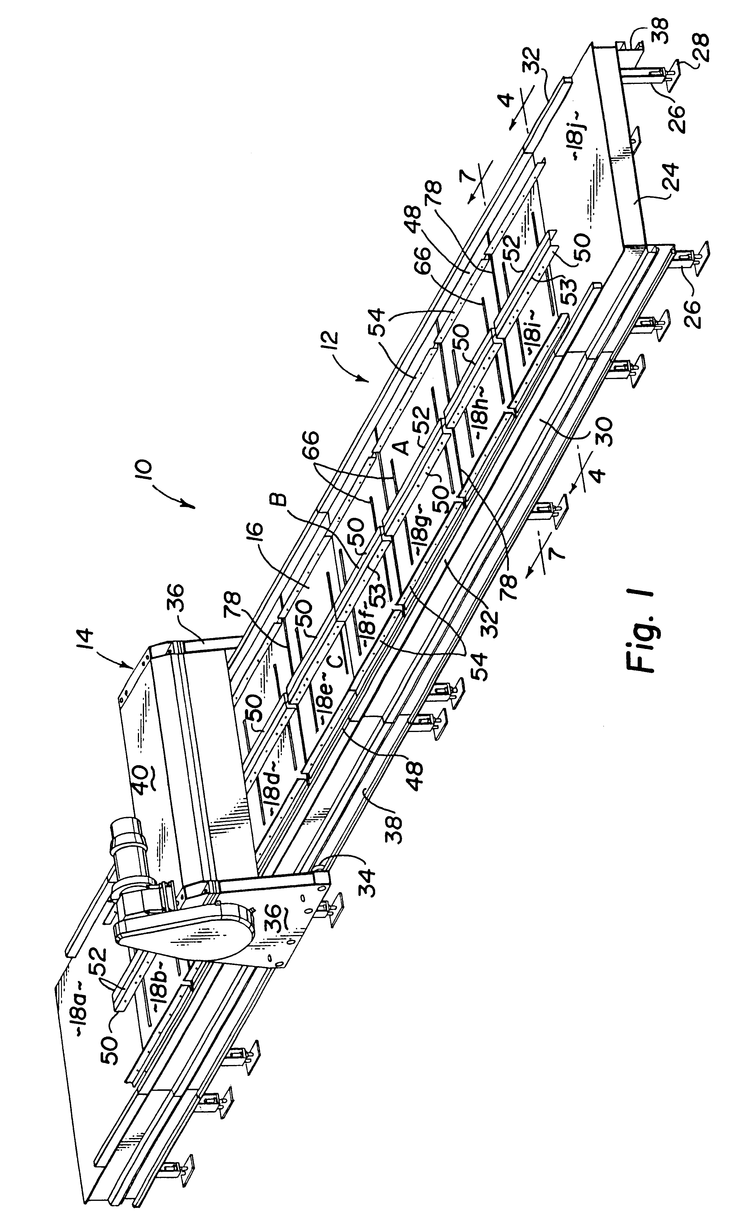
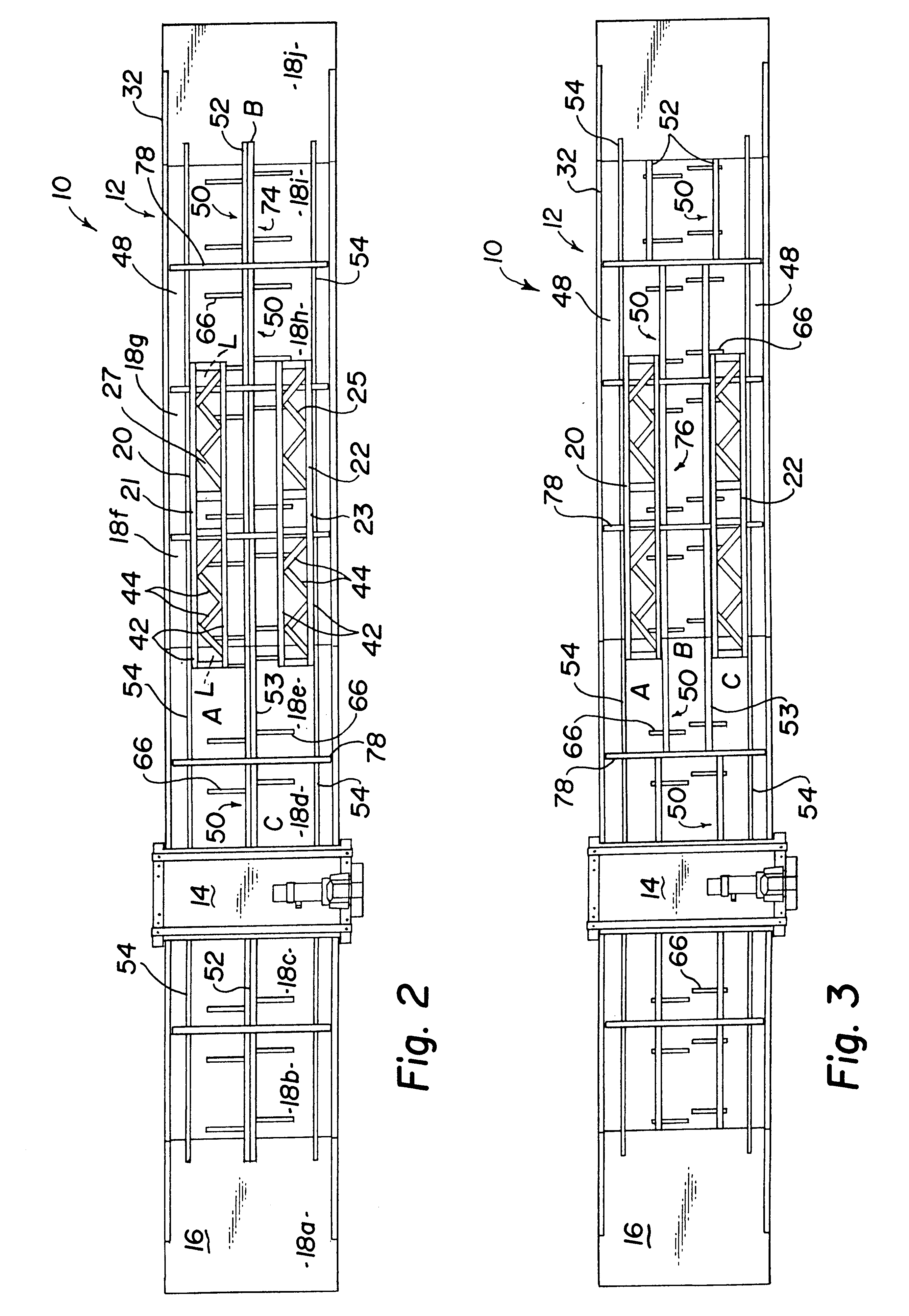
FIGS. 1 and 2 show a truss assembly apparatus 10 for semi-automatic manufacture of prefabricated structural components, particularly wooden trusses and joists. The truss assembly apparatus 10 comprises a truss table 12 and a table gantry press 14 supported on the table for movement there along.

The work surface 16 of the truss table 12 is defined by table plates 18a-j, which are arranged end-to-end. Table plates 18b-i provide working space for assembly of the trusses 20 and 22, while plates 18a and 18j provide staging areas for the table gantry press 14. The table may be designed to any desired length. The plates 18 are supported by a plurality of cross-members 24 which are mounted to the legs 26 of the table. Each leg 26 o...


PUM

PropertyMeasurementUnit
movementaaaaaaaaaa
dimensionsaaaaaaaaaa
lengthaaaaaaaaaa

Abstract

A truss assembly apparatus and method for assembling a truss utilizing the apparatus are presented, the apparatus comprising a truss table having a work surface with a first and second assembly zone. A first clamping assembly has a movable first clamp rail for clamping the truss in the first assembly zone, the first clamp rail having at least one flip-arm recess therein. A flip-over assembly has at least one flip-over arm movable relative to the work surface for moving the truss from a first truss position-in the first assembly zone to a second truss position in the second assembly zone, the flip-over arm movable into the flip-arm recess of the first clamp rail. The apparatus may have a plurality of such recesses and flip arms. The truss assembly apparatus may further comprise a second clamping assembly having a movable second clamp rail for clamping the truss in the second assembly zone, the second clamp rail having a flip-arm recess therein movable into the flip-arm recess of the second clamp rail.

Description

The present invention relates in general to improvements in apparatus and methods for fabricating structural components. More particularly, this invention concerns a truss assembly apparatus and method having an automated truss movement assembly.BACKGROUND OF INVENTIONPrefabricated building components, now widely utilized in the construction industry, are typically assembled at a manufacturing facility and then transported to the job site for incorporation into a building structure. Prefabricated trusses for use as roof or floor supports are assembled from pre-cut wooden chord and web members positioned in abutting relationship and connected together using toothed fastener plates.Truss assembly devices have been developed for performing this task semi-automatically. The pre-cut wooden members are positioned manually over a support surface and clamped in place, after which connector plates are laid over the abutting joints. The connector plates are then embedded into the members with...

Claims


Application Information

Patent Timeline
Patent Type & Authority Patents(United States)
IPC IPC(8): B23Q1/00B23Q1/03B27F7/15B27F7/00
CPCB23Q1/032B27F7/155Y10S269/91Y10T29/53317Y10T29/53417Y10T29/5397Y10T29/49625Y10T29/49829Y10T29/49902Y10T29/53383Y10T29/49899Y10T29/5343Y10T29/49833Y10T29/49828
Inventor MCADOO, DAVID L.
Owner ILLINOIS TOOL WORKS INC
Why Eureka
Try Eureka