Electrical junction box cover assembly

a technology of junction box and assembly, which is applied in the direction of coupling device connection, coupling device details, printed circuits, etc., can solve the problems of wires extending, top cover may not latch to the mounting cover properly, and interfere with the top cover

Inactive Publication Date: 2003-05-13
SUMITOMO WIRING SYST LTD
View PDF11 Cites 24 Cited by
  • Summary
  • Abstract
  • Description
  • Claims
  • Application Information

AI Technical Summary

Problems solved by technology

One disadvantage of these electrical junction boxes and connectors is that, if the junction box is placed in a mounting cover, the wires may interfere with a top cover and the top cover may not properly latch to the mounting cover during assembly.
Another disadvantage is that the wires may extend from between the mounting cover and top cover at any location.
Yet another disadvantage is that the wires may extend away from the mounting cover and are free to move, which is undesired.
However, only one wire is retained and a large amount of force is needed to dispose the wire between the arms to retain the wire, which is undesired.
Further, the wire retention mechanism is not provided adjacent a wire housing exit.

Method used


Image

  • Electrical junction box cover assembly
  • Electrical junction box cover assembly
  • Electrical junction box cover assembly

Examples


Embodiment Construction

)

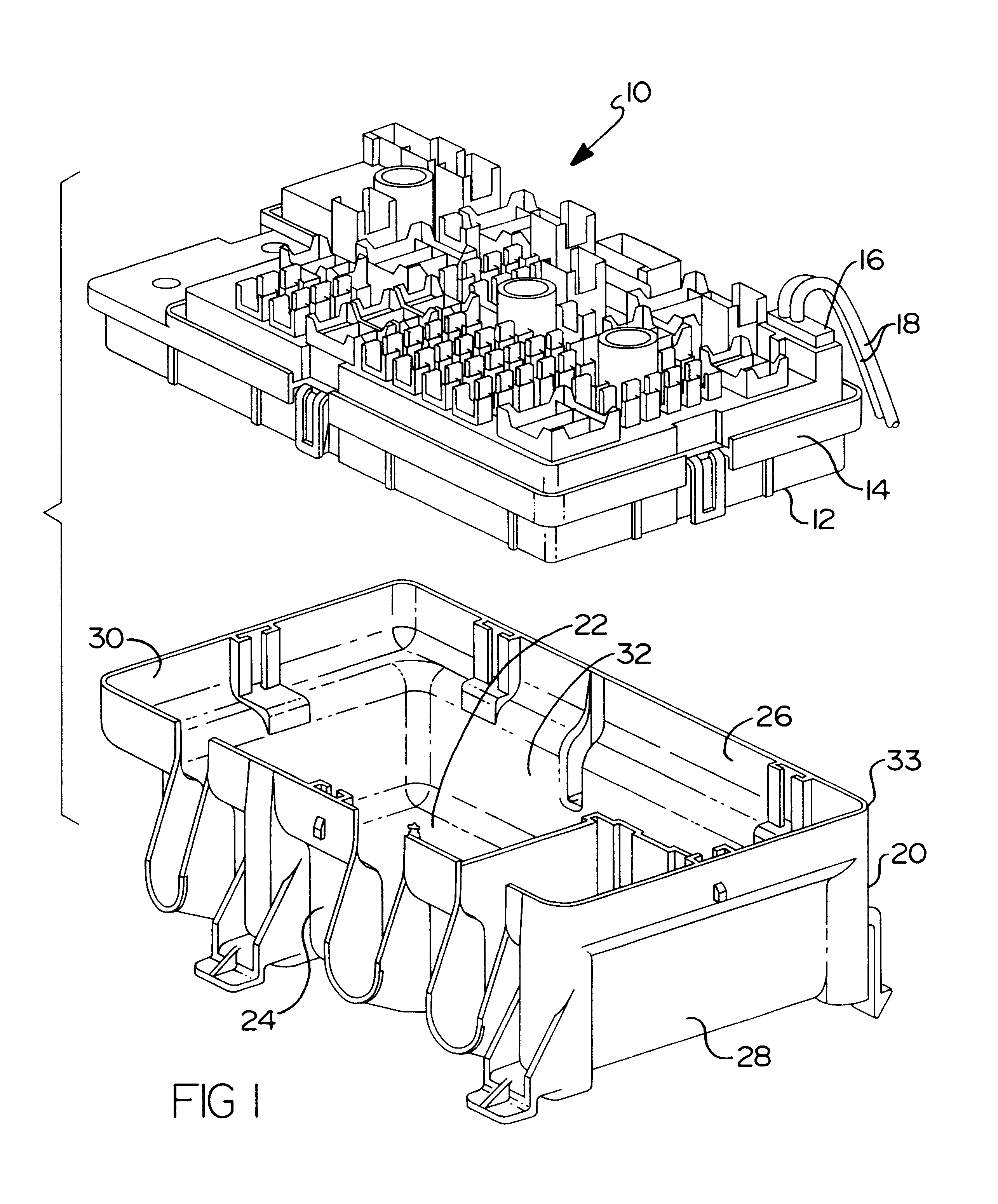
Referring to FIGS. 1 and 2, an electrical junction box cover assembly 10, according to the present invention, is shown for a motor vehicle (not shown). The electrical junction box cover assembly 10 includes a junction box 12 having a generally "T" shaped flange 14 for a function to be described. The junction box 12 is generally rectangular in shape. The electrical junction box cover assembly 10 includes at least one electrical connector 16 connected thereto. The electrical connector 16 has at least one, preferably a plurality of electrical wires 18 extending therefrom. The electrical wires 18 are a predetermined gauge of wire such as ten (10) gauge. The junction box 12 is preferably a one-piece molded plastic member. It should be appreciated that the junction box 12, electrical connector 16, and electrical wires 18 are conventional and known in the art.

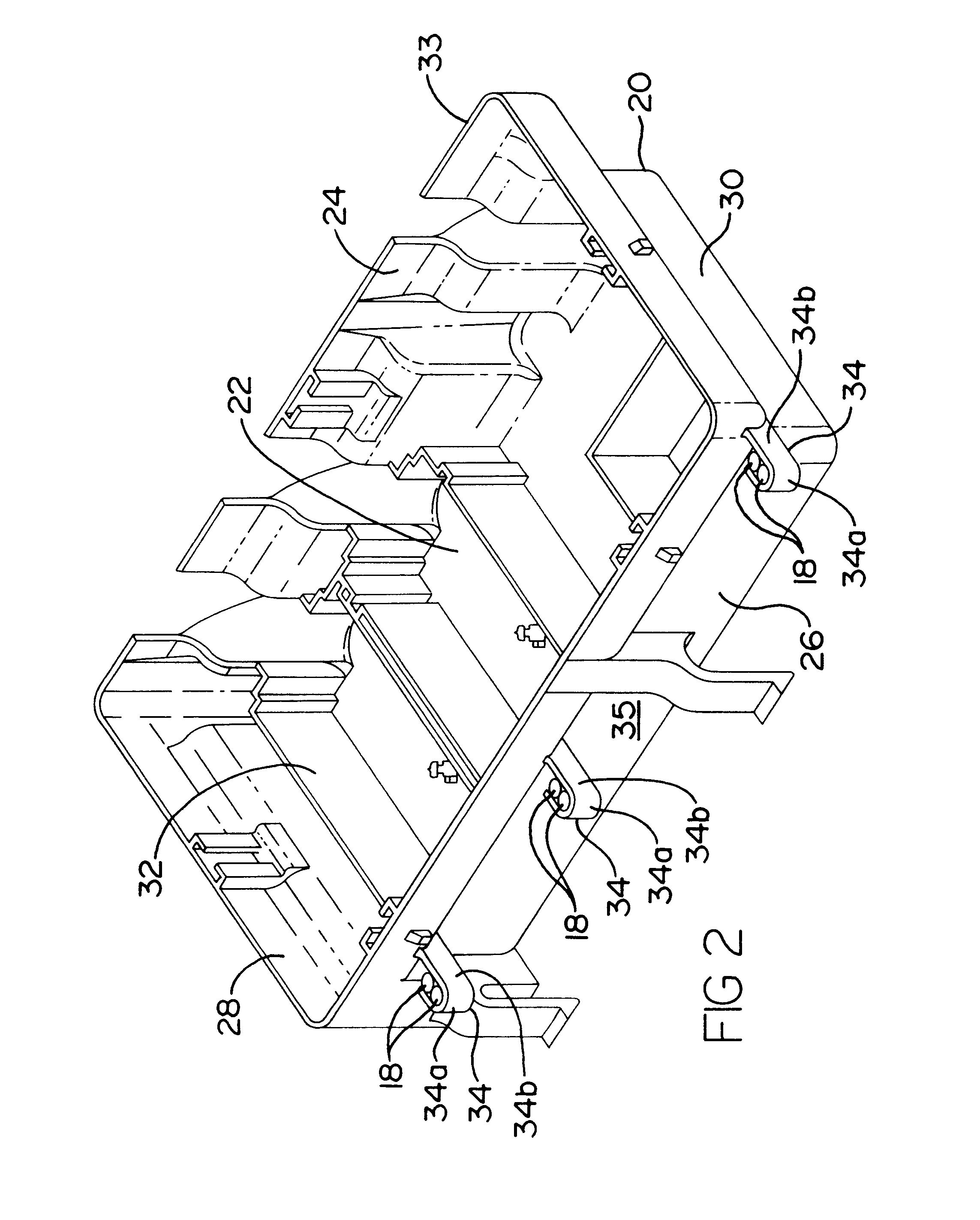
Referring to FIGS. 1 and 2, the electrical junction box cover assembly 10 includes a mounting cover 20 for receiving the junction b...


PUM


Abstract

An electrical junction box cover assembly for a motor vehicle includes a mounting cover and a junction box at least partially disposed in the mounting cover. The electrical junction box cover assembly also includes a connector connected to the junction box and having at least one wire extending therefrom out of the mounting cover. The electrical junction box cover assembly includes a top cover connected to the mounting cover with the at least one wire extending therebetween. The electrical junction box cover assembly further includes at least one clip extending from either one of the mounting cover and the junction box past an outer surface of the mounting cover to retain the at least one wire in a predetermined position relative thereto.

Description

1. Field of the InventionThe present invention relates generally to electrical junction boxes and, more particularly, to an electrical junction box cover assembly for a motor vehicle.2. Description of the Related ArtElectrical junction boxes and connectors have been provided to connect and retain wires together on a motor vehicle. These electrical junction boxes typically have electrical connectors connected thereto with wires extending from the electrical connectors.One disadvantage of these electrical junction boxes and connectors is that, if the junction box is placed in a mounting cover, the wires may interfere with a top cover and the top cover may not properly latch to the mounting cover during assembly. Another disadvantage is that the wires may extend from between the mounting cover and top cover at any location. Yet another disadvantage is that the wires may extend away from the mounting cover and are free to move, which is undesired.It is known to provide a wire retention ...

Claims


Application Information

Patent Timeline
Patent Type & Authority Patents(United States)
IPC IPC(8): H05K7/02
CPCH05K7/026
Inventor DEPP, CHARLESMALCOM, BENNIESINGH, NANCY
Owner SUMITOMO WIRING SYST LTD
Why Eureka
Try Eureka