Method for forming a device having a cavity with controlled atmosphere

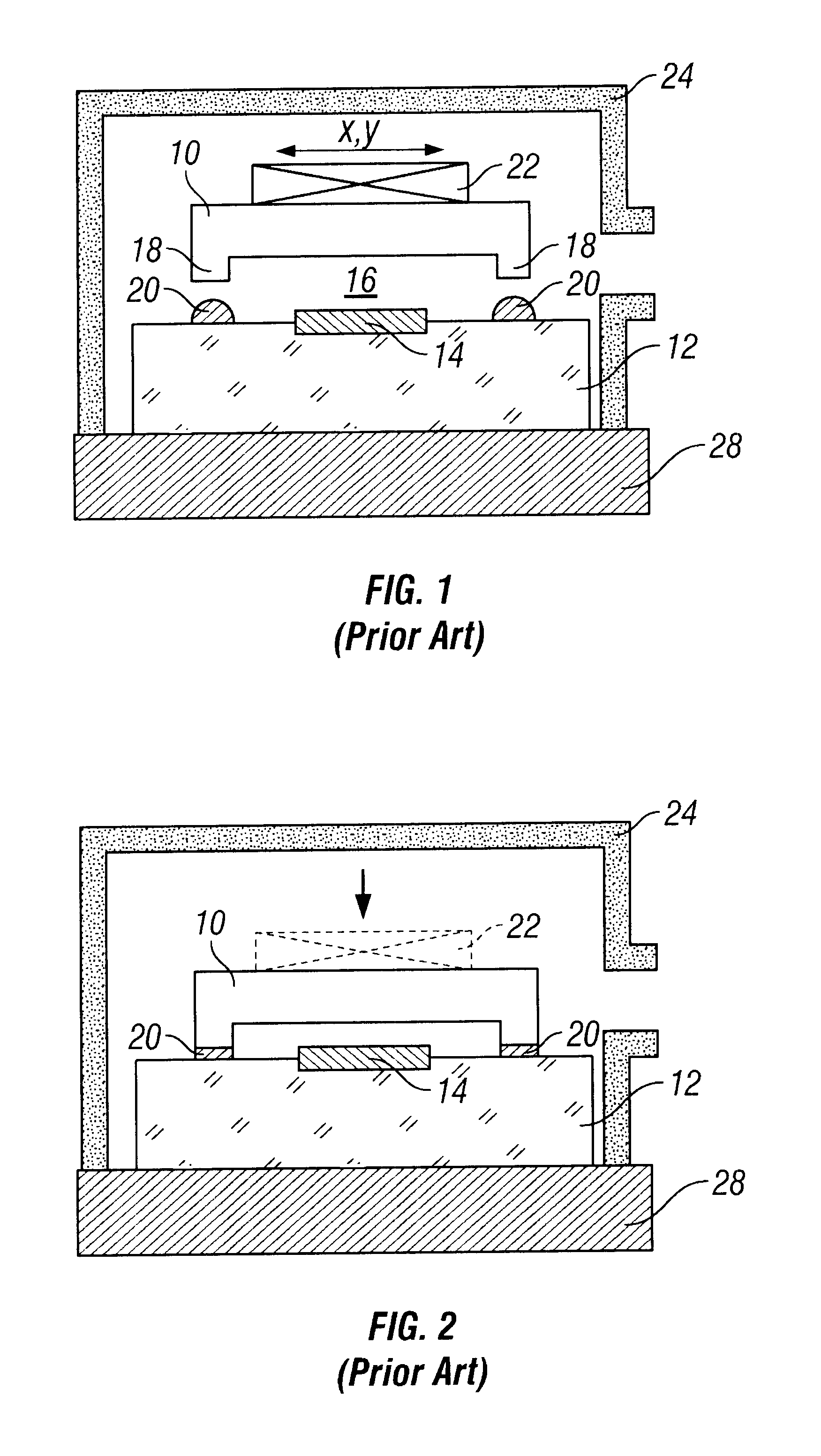
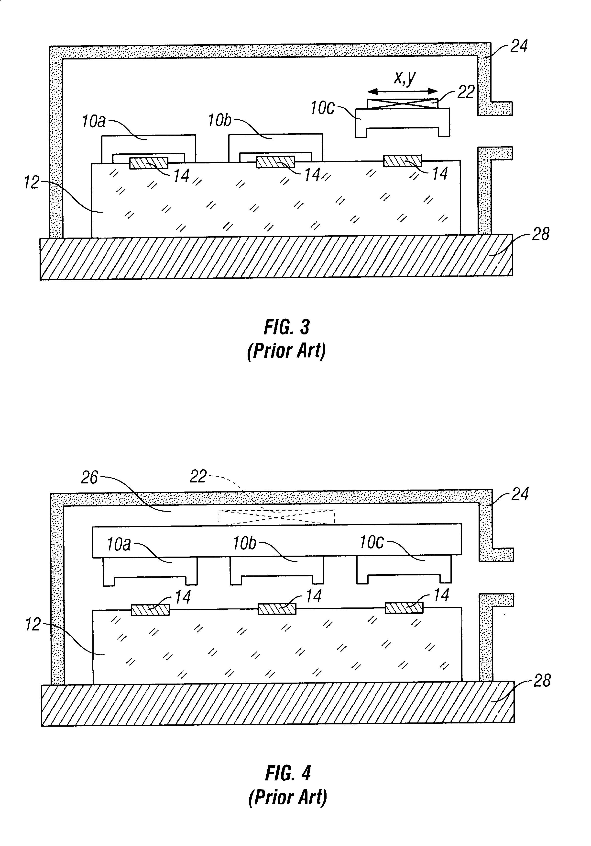
a technology of controlled atmosphere and cavity, which is applied in the direction of microstructure, microstructure, and sintering apparatus, etc., can solve the problems of inability to control the atmosphere precisely, the gas passage between the cover and the carrier is hindered, and the housing is difficult to achiev

Inactive Publication Date: 2003-05-20
COMMISSARIAT A LENERGIE ATOMIQUE ET AUX ENERGIES ALTERNATIVES
View PDF8 Cites 58 Cited by
  • Summary
  • Abstract
  • Description
  • Claims
  • Application Information

AI Technical Summary

Problems solved by technology

The method described with reference to FIG. 3 therefore raises housing problems of the alignment means, and proves to be little adapted to the positioning of a high number of covers onto a carrier.
For when the cover is placed on the carrier previous to placing the assembly forme

Method used


Image

  • Method for forming a device having a cavity with controlled atmosphere
  • Method for forming a device having a cavity with controlled atmosphere
  • Method for forming a device having a cavity with controlled atmosphere

Examples


Embodiment Construction

The purpose of the present invention is to put forward a method for encapsulating one or more components, which does not have the difficulties or constraints described above.

The method is intended to encapsulate components which may either be previously applied to a substrate or directly integrated into the substrate (electronic chips, integrated sensors . . . ).

One purpose of the invention in particular is to provide such a method which may be conducted in a chamber with a controlled atmosphere free of means to align the covers on the components.

A further purpose is to provide such a method with which it is possible to align with precision and to bond collectively a great number of covers over corresponding components.

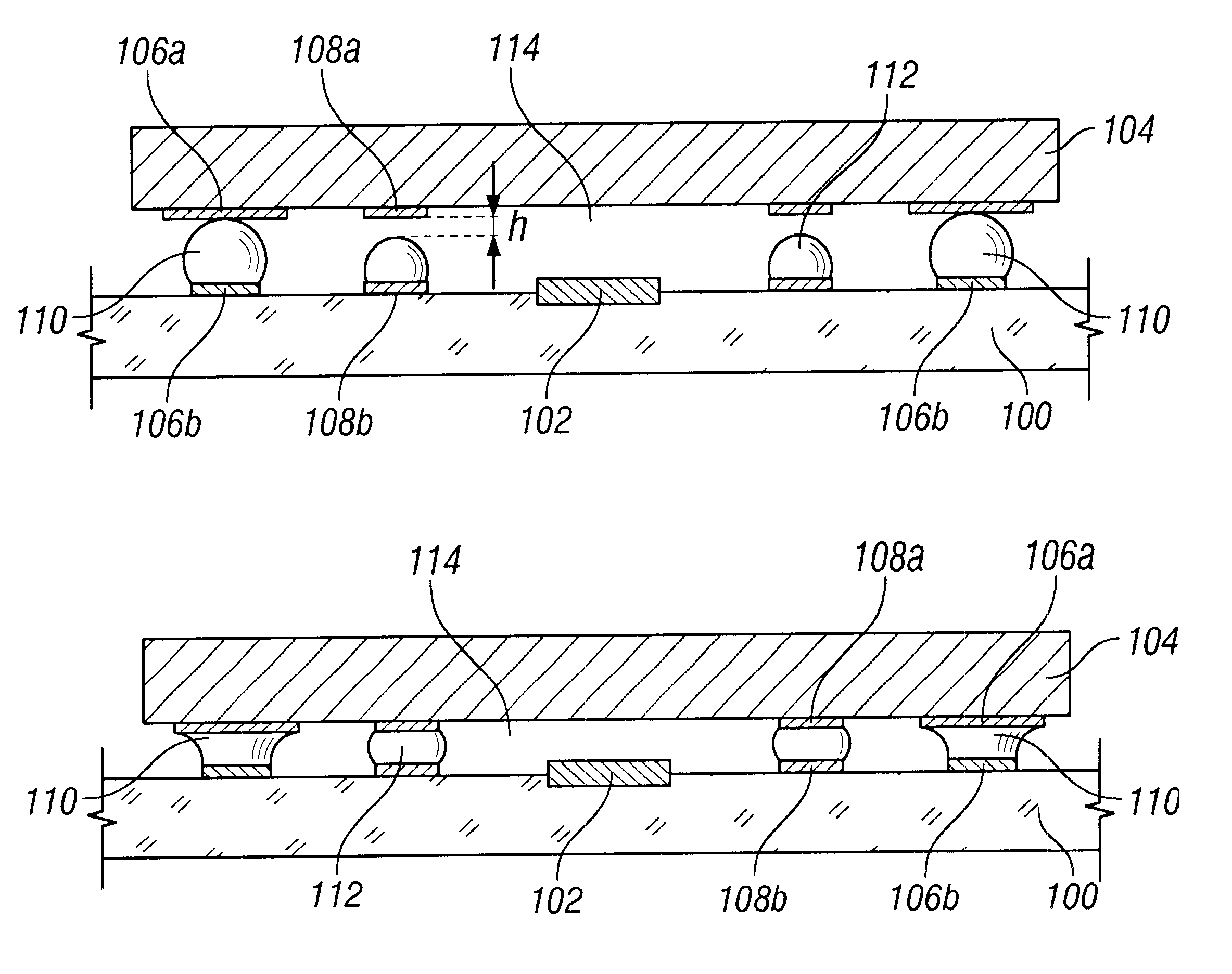
To attain these purposes, the subject of the invention is more precisely an encapsulation method in a controlled atmosphere of at least one component by bonding at least one cover onto at least one region of a carrier containing the component. In accordance with the m...


PUM

PropertyMeasurementUnit
Temperatureaaaaaaaaaa
Areaaaaaaaaaaa
Heightaaaaaaaaaa

Abstract

Device comprising a carrier (100) and at least one cover (104) able to be bonded to the carrier to form with the carrier at least one cavity (114) having a controlled atmosphere around at least one component (102). In accordance with the invention, at least one of either the cover or the carrier is provided with at least one wedge (110) in fusible material and a strip of insulation (112) formed around said component, and before bonding, the wedge of fusible material is of sufficient thickness to prevent the strip of insulation (112) from coming into contact both with the cover and with the carrier when they are assembled together.Particular application to the encapsulation of electronic, mechanical or electromagnetic components.

Description

"This application is a national phase of PCT / FR99 / 01457 which was filed on Jun. 17, 1999 and was not published in English."The present invention relates to a method for encapsulating components and for forming a device having one or more components arranged in one or more cavities with a controlled atmosphere.By cavity, with controlled atmosphere is meant both a cavity in which a vacuum has been set up and a cavity containing a gas with controlled composition and / or pressure.Said cavity, defined for example by a cover applied to a substrate, can be used to house sensitive components such as electronic, electro-optic or micro-mechanical components.In particular, the invention finds applications in the hermetic encapsulation of electronic chips, of pressure or acceleration sensors, or further of electromagnetic sensors such as bolometer sensors.STATE OF THE PRIOR ARTDifferent techniques are known with which it is possible to bond a cover onto a carrier. For example glass bonding techn...

Claims


Application Information

Patent Timeline
IPC IPC(8): B81B7/00H01L21/02H01L21/50H01L23/10H01L23/02B81C3/00
CPCB81C1/00269B81C3/002H01L21/50H01L23/10B81C2203/019B81C2203/032H01L2224/81191H01L2924/01079H01L2924/16152H01L2224/73103H01L2924/00012H01L2224/29011H01L2224/29013H01L2224/73203
Inventor MARION, FRAN.CEDILLA.OISPORNIN, JEAN-LOUISMASSIT, CLAUDECAILLAT, PATRICE
Owner COMMISSARIAT A LENERGIE ATOMIQUE ET AUX ENERGIES ALTERNATIVES
Why Eureka
Try Eureka