

Omega firearms suppressor
a suppressor and omega technology, applied in the field of sound suppressor devices, can solve the problems of only working well with one caliber of ammunition, affecting the accuracy of the host firearm, and not achieving high noise and flash attenuation of the suppressor device,
- Summary
- Abstract
- Description
- Claims
- Application Information
AI Technical Summary
Problems solved by technology
Method used
Image

Examples
first embodiment
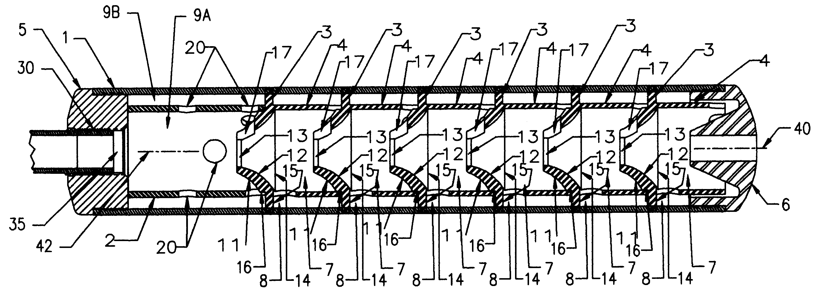
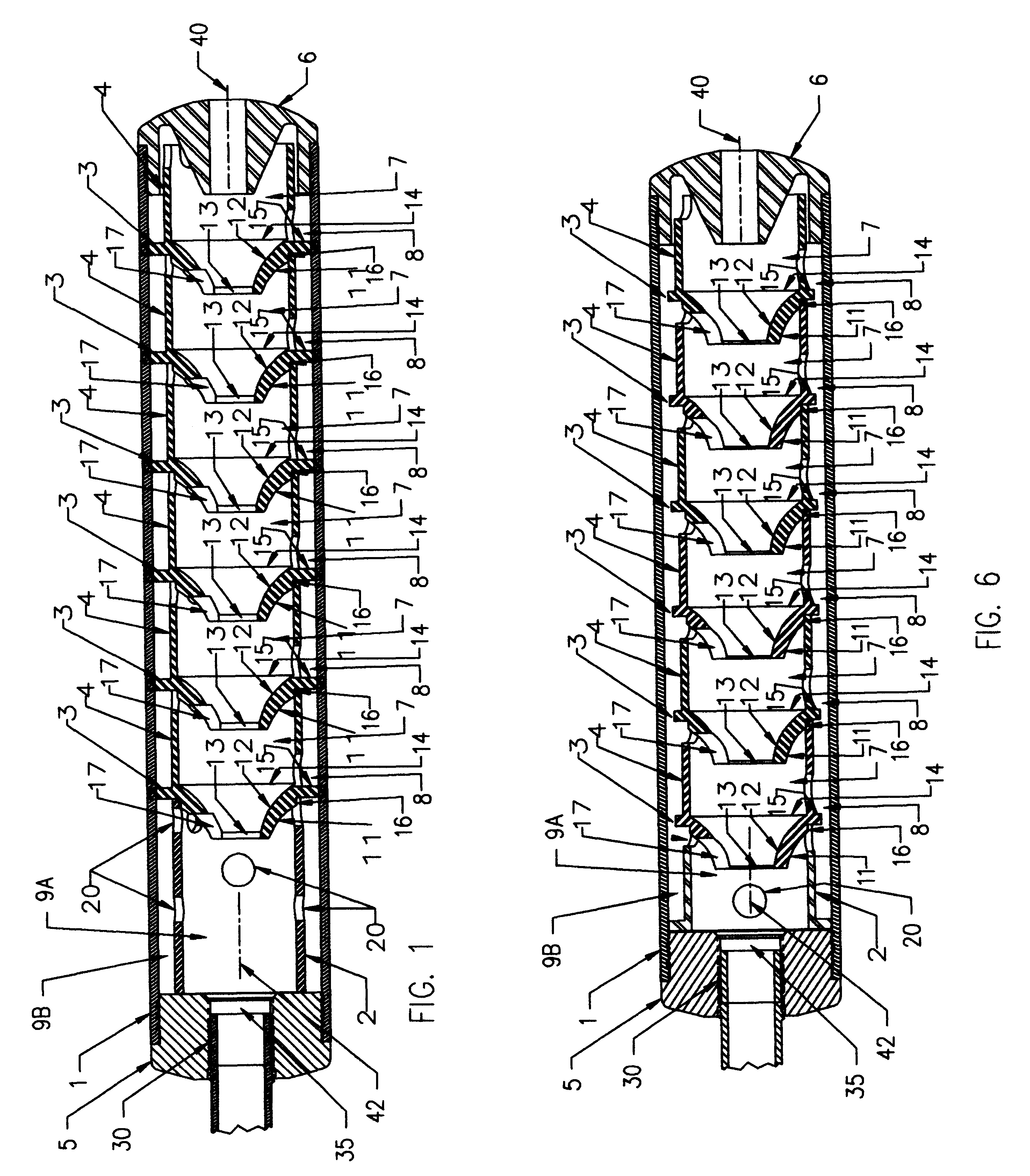
FIG. 1 shows the sound suppressor that consists of a hollow cylindrical housing 1 with baffle elements 3 and coaxial spacer elements 4 forming a series of expansion chambers 7 and 8 between the baffle elements 3. A rear end cap 5 and a front end cap 6 are secured to the housing 1, either by screw threads which are not shown or by welding the end caps 5 and 6 to the housing 1.
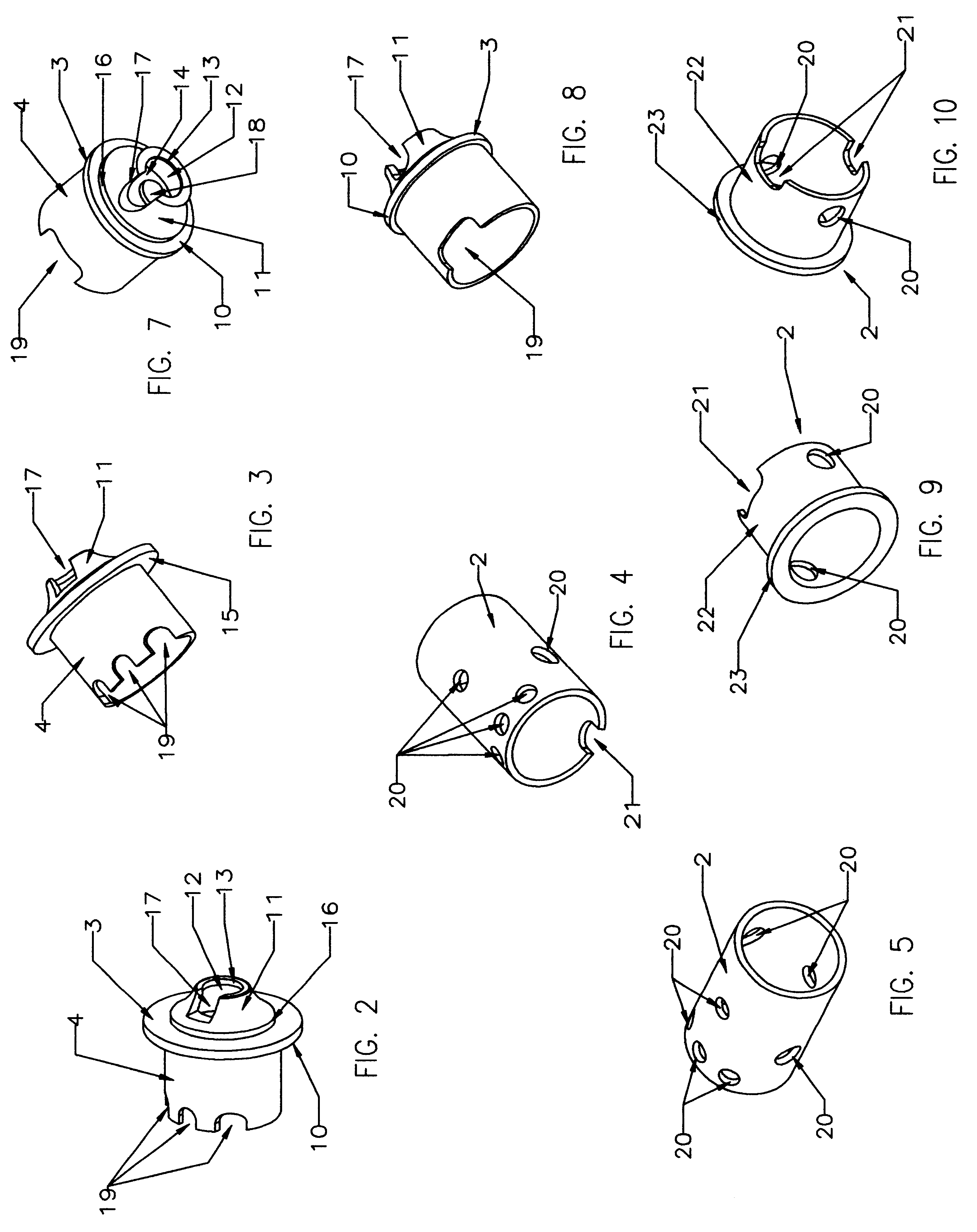
An initial coaxial spacer element 2 is positioned between the rear end cap 5 and a baffle element 3 and this forms two initial gas expansion chambers 9a and 9b. Baffle element 3 consists of a flat plate 10 with an integral rearward protruding cone 11 with the apex of the conical surface pointing towards the muzzle of the firearm and the cone 11 having an internal conical surface 12 and a bore aperture 13. Cone 11 has an opening 14 on the front face 15 of the baffle element. An annular shoulder 16 is provided to allow for the initial coaxial spacer element 2 and coaxial spacer element 4 to interface with the baff...
second embodiment
DETAILED DESCRIPTION OF THE INVENTION
FIG. 6 shows a second embodiment of the sound suppressor that consists of a hollow cylindrical housing 1 with baffle elements 3 and coaxial spacer elements 4 forming a series of expansion chambers 7 and 8 between the baffle elements 3. A rear end cap 5 and a front end cap 6 is secured to the housing 1, either by screw threads which are not shown or by welding the end caps 5 and 6 to the housing 1.
An initial coaxial spacer element 2 is positioned between the rear end cap 5 and a baffle element 3 and this forms two initial gas expansion chambers 9a and 9b. Baffle element 3 consists of a flat plate 10 with an integral rearward protruding cone 11 with the apex of the conical surface pointing towards the muzzle of the firearm and the cone 11 having an internal conical surface 12 and a bore aperture 13 and cone 11 has an opening 14 on the front face 15 of the baffle element. An annular shoulder 16 is provided to allow for the initial coaxial spacer ele...
PUM
 Abstract
Description
Claims
Application Information