
Rate matching method

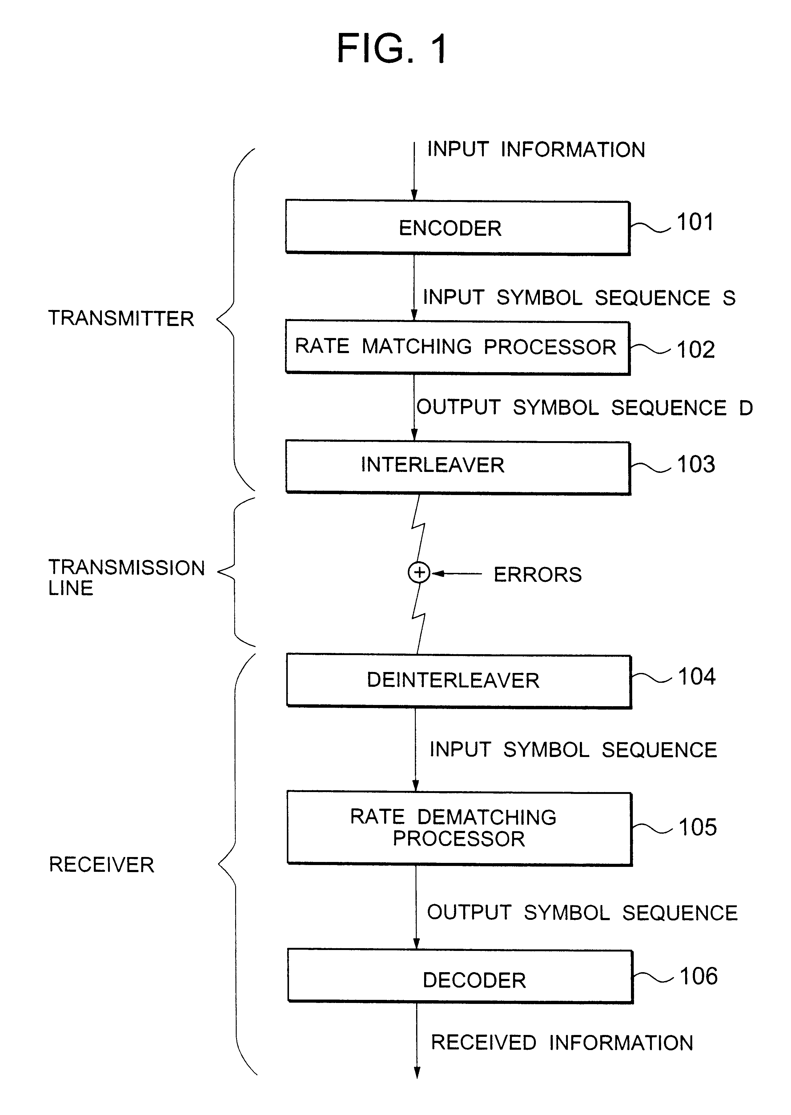
a rate matching and rate technology, applied in the field of digital communication systems, can solve the problems of reducing the error rate of symbols more than the constraint length away from the symbol, many decoding systems are susceptible to an error burst, and cannot fully exhibit the error correction capability

Inactive Publication Date: 2003-06-17
NEC CORP
View PDF4 Cites 20 Cited by
  • Summary
  • Abstract
  • Description
  • Claims
  • Application Information

AI Technical Summary

Benefits of technology

An object of the present invention is to provide a rate matching method that can achieve more reliable data communication.
Preferably, the second symbol string d(j) is interleaved and then transmitted and the first symbol string S(k) is produced by deinterleaving a received symbol string.

Problems solved by technology

In general, many decoding systems are susceptible to an error burst, and when a number of symbols have been consecutively deleted as mentioned above, they cannot fully exhibit the error correction capability.
In the case of the convolution code, however, the reduction in error rate for symbols more than the constraint length away from that symbol cannot be expected at all.
It will be understood from the example shown in FIGS. 15A-15D that each deleting operation (steps (a)-(e)) provides the maximum interval between deleted symbols, resulting in optimum deletion processing, but the optimum deletion processing is not always performed between deleting operations because the relation between the current and the previous deleting operations is not sufficiently taken into account.
There is a high possibility that the symbol sequence deleted like this causes problems when demodulated and decoded.
Similarly, in the case of symbol-repetition rate matching, the positions of repeated symbols may be distributed unevenly, producing a symbol region susceptible to error and a symbol region resistant to error.

Method used


Image

  • Rate matching method
  • Rate matching method
  • Rate matching method

Examples


example 1-1

Symbol Deletion

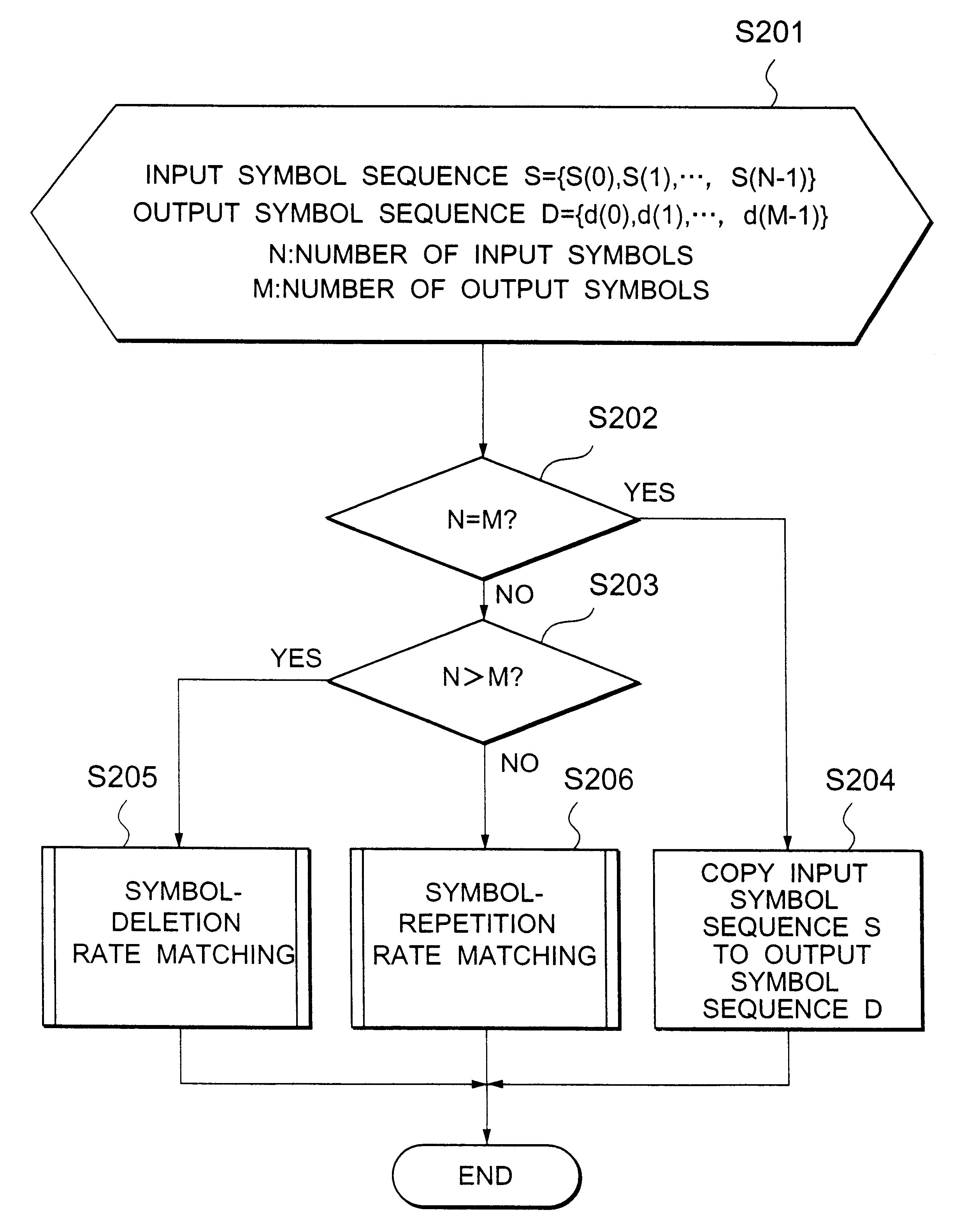
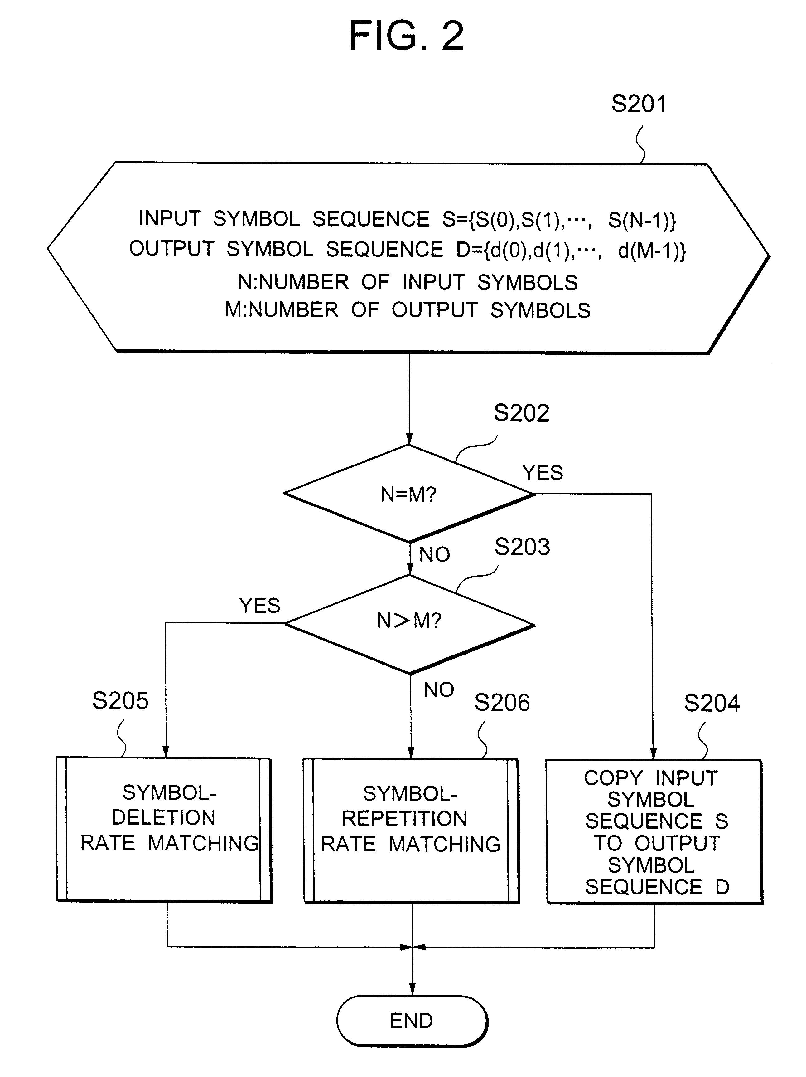
Referring to FIG. 6, in the case of q=2, N=128 and M=100, the step S307 is performed when R is not identical to 2 and, only when R=2, the step S307 is skipped. In other words, as shown in FIG. 6, the 28 symbols included in the row of R=2 are not copied, resulting in the output symbol string D={1, 2, 4, 5, 6, 7, 9, 10, 11, 12, 14, 15, . . . , 125, 126, 128}. The symbols of any row can be deleted by selecting the corresponding value of q.

example 1-2

Symbol Deletion

Another way may be used to delete N-M symbols. The same advantage can be obtained by determining the distance of a symbol from the bottom symbol for each column. More specifically, the distance (p) of a symbol from the bottom symbol is selected from {0, 1, 2, 3}. Thereafter, by comparing R and p for earn C, it is determined whether the corresponding symbol should be copied, in other words, the step S307 of FIG. 3 should be skipped.

Referring to FIG. 7A, in the case of p=0, the respective last symbols of the columns {5, 10, 14, 19, 23, 28, . . . , 115, 119, 124, 128} are deleted from the input symbol string S.

Referring to FIG. 7B, in the case of p-2, the respective last-but-two symbols of the columns {3, 8, 12, 17, 21, 26, . . . , 113, 117, 122, 126} are deleted from the input symbol string S.

As described above, according to the present embodiment, the narrowest interval and the widest interval between deleted symbols are almost the same. Precisely, the narrowest interv...

example 1-3

Symbol Repetition

Referring to FIG. 8, in the case of q=2, N=128 and M=156, the step S410 is performed only when R is identical to 2 and, when R is not identical to 2, the step S410 is skipped. In other words, as shown in FIG. 8, only the 28 symbols included in the row of R-2 are copied, resulting in the output symbol string D-{1, 2, 3, 3, 4, 5, 6, 7, 8, 8, 9, 10, 11, 12, 13, 13, 14, 15, . . . , 125, 126, 127, 127, 128}. The symbols of any row can be repeated by selecting the corresponding value of q.


PUM


Abstract

A rate matching method allowing reliable digital communication is disclosed. After setting D=|n-m| and Q=n / D, the input symbol string is sequentially divided to produce D symbol strings each consisting of either Q symbols or (Q+1) symbols so as to arrange the input symbols in an arrangement of columns (C) and rows (R). Then, after selecting a single symbol located at a predetermined position for each of the D symbol strings, the output symbol string is provided by deleting the single symbol for each of the D symbol strings when n>m or repeating the single symbol for each of the D symbol strings when n<m.

Description

1. Field of the InventionThe present invention generally relates to a digital communication system, and in particular to a rate matching method for producing an output string of m symbols from an input string of n (n-m) symbols2. Description of the Related ArtIn the field of digital communication systems, there have been proposed several rate matching methods for obtaining output sequence of m symbols from input sequence of n symbols. In the case of n>m, the first (n-m) symbols of the input symbol string are deleted to produce the output string of the remaining m symbols. In the case of n<m, after repeating a top input symbol (m-n+1) times, m symbols following the top input symbol are output to produce the output string of m symbol.In the case of the symbol sequence encoded with a convolution code, it is known that the original information can be reproduced correctly, even if the symbol sequence has been partly deleted, by inserting dummy symbols into the imperfect symbol sequ...

Claims


Application Information

Patent Timeline
Patent Type & Authority Patents(United States)
IPC IPC(8): H04L5/14H03M13/23H03M13/41H04L7/00H03M13/00H04L1/00H03M13/27H04L27/02H04B7/26H04L27/04H04B1/69
CPCH03M13/2707H03M13/6362H03M13/6356H03M13/2792H03M13/23H04B1/69H03M13/00
Inventor TSUMURA, SOICHI
Owner NEC CORP
Learn More