Object supporting structure

a technology for supporting structures and objects, applied in the direction of machine supports, building scaffolds, other domestic objects, etc., can solve the problem of excessive loading charge, and achieve the effect of discharging the loading charge of load elements

Inactive Publication Date: 2003-07-15
LI CHIN CHU
View PDF5 Cites 195 Cited by
  • Summary
  • Abstract
  • Description
  • Claims
  • Application Information

AI Technical Summary

Problems solved by technology

However, the construction of the above supporting structure produces an excessive loading charge exerted on the connecting element 12a.

Method used


Image

  • Object supporting structure
  • Object supporting structure
  • Object supporting structure

Examples


Embodiment Construction

Wherever possible in the following description, like reference numerals will refer to like elements and parts unless otherwise illustrated.

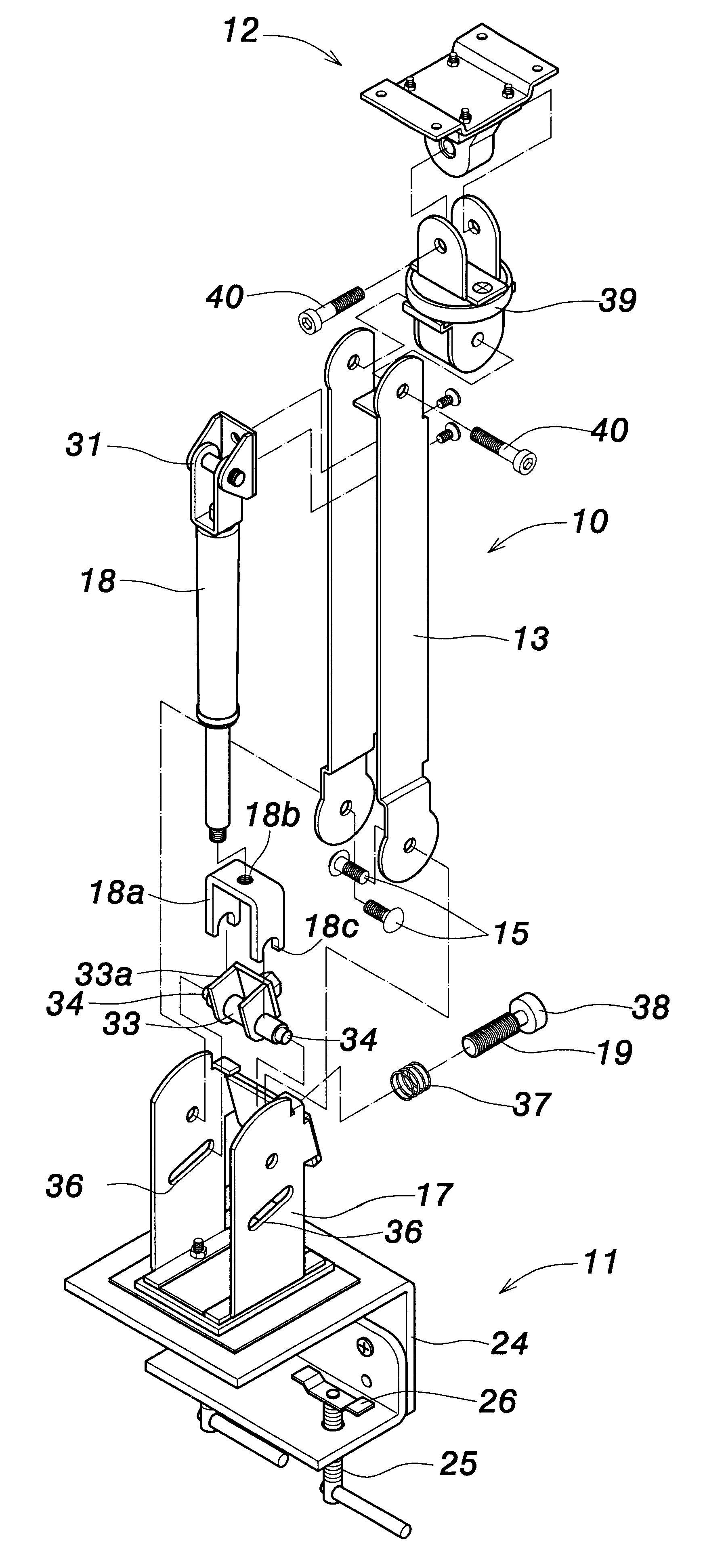
Referring to FIG. 3 through FIG. 6, the invention provides an object supporting structure the construction of which includes a carrier arm 10, a clamping base 11, and a socle 12.

The carrier arm 10 comprises two arm bodies 13, 14 that assemble with each other in a manner to form a hollow body. A lower end of each arm body 13, 14 is pivotally connected to an attachment block 17 via hinges 15, 16. The carrier arm 10 internally includes a load element 18 that is, for example, a pneumatic jack. An extendable and retractable rod mounted at an upper end of the load element 18 is connected to a connecting part 31 inside the arm body 13. A lower end of the load element 18 is connected via a fulcrum assembly to the attachment block 17. The fulcrum assembly (detailed hereafter) comprises a threaded rod position adjuster 19 that, by rotation, varies the supp...


PUM


Abstract

An object supporting structure includes a load element that is downwardly connected to a first U-shaped piece that is connected by abutment to a sliding axle of a connecting element. The connecting element is provided with a second U-shaped piece that is placed inside the first U-shaped piece. Thereby, a loading charge of the load element is uniformly distributed on the connecting element by means of the first and second U-shaped pieces. As a result, the loading charge from the load element is dissipated, which prevents the connecting element from receiving an excessive loading charge so that the sliding axle can favorably slide along the grooves of the attachment base.

Description

1. Field of the InventionThe invention relates to an object supporting structure and, more particularly, to an object supporting structure that can be easily slidably adjusted.2. Description of the Related ArtFIG. 1 and FIG. 2 illustrate an object supporting structure of the prior art that is disclosed in U.S. Pat. No. 5,799,917, which is incorporated herein by reference. The supporting structure principally comprises a carrier arm 10a that inwardly includes a load element 11a (such as a pneumatic jack or spring), and is downwardly connected to an attachment block 14a. The load element 11a is downwardly connected to a connecting element 12a that is provided with a sliding axle 13a that inserts through left and right grooves 15a formed through two sides of the attachment block 14a. The load element 11a can be thereby slidably adjusted.However, the construction of the above supporting structure produces an excessive loading charge exerted on the connecting element 12a. The sliding axl...

Claims


Application Information

Patent Timeline
Patent Type & Authority Patents(United States)
IPC IPC(8): F16M11/04F16M11/02
CPCF16M11/04F16M11/2092F16M11/24F16M13/00F16M13/022F16M2200/044F16M2200/063Y10S248/921
Inventor LI, CHIN-CHU
Owner LI CHIN CHU
Why Eureka
Try Eureka