Power unit for automotive trunk lid

a technology for power units and trunk lids, which is applied in the direction of roofs, wing accessories, transportation and packaging, etc., can solve the problems of reducing the effective luggage receiving capacity of the trunk room, and it is difficult to properly mount the power unit on the right position of the vehicle body

Inactive Publication Date: 2003-08-05
MITSUI KINZOKU ACT
View PDF4 Cites 46 Cited by
  • Summary
  • Abstract
  • Description
  • Claims
  • Application Information

AI Technical Summary

Benefits of technology

It is still another object of the present invention to provide a power unit for an automotive trunk lid, wherein essential parts of the power unit are mounted on both side surfaces of a base plate to achieve a balanced mounting of the parts.

Problems solved by technology

However, the power unit of the publication fails to have a compact construction, which thus causes a considerable reduction in an effective luggage receiving capacity of the trunk room.
Furthermore, in the power unit of the publication, it is difficult to properly mount the power unit on a right position of the vehicle body in a short time because it tends to occur that some of the movable parts of the power unit make a free movement when an assembler is handling the power unit to mount the same to the right position.

Method used


Image

  • Power unit for automotive trunk lid
  • Power unit for automotive trunk lid
  • Power unit for automotive trunk lid

Examples


Embodiment Construction

In the following, an embodiment of the present invention will be described with reference to the accompanying drawings.

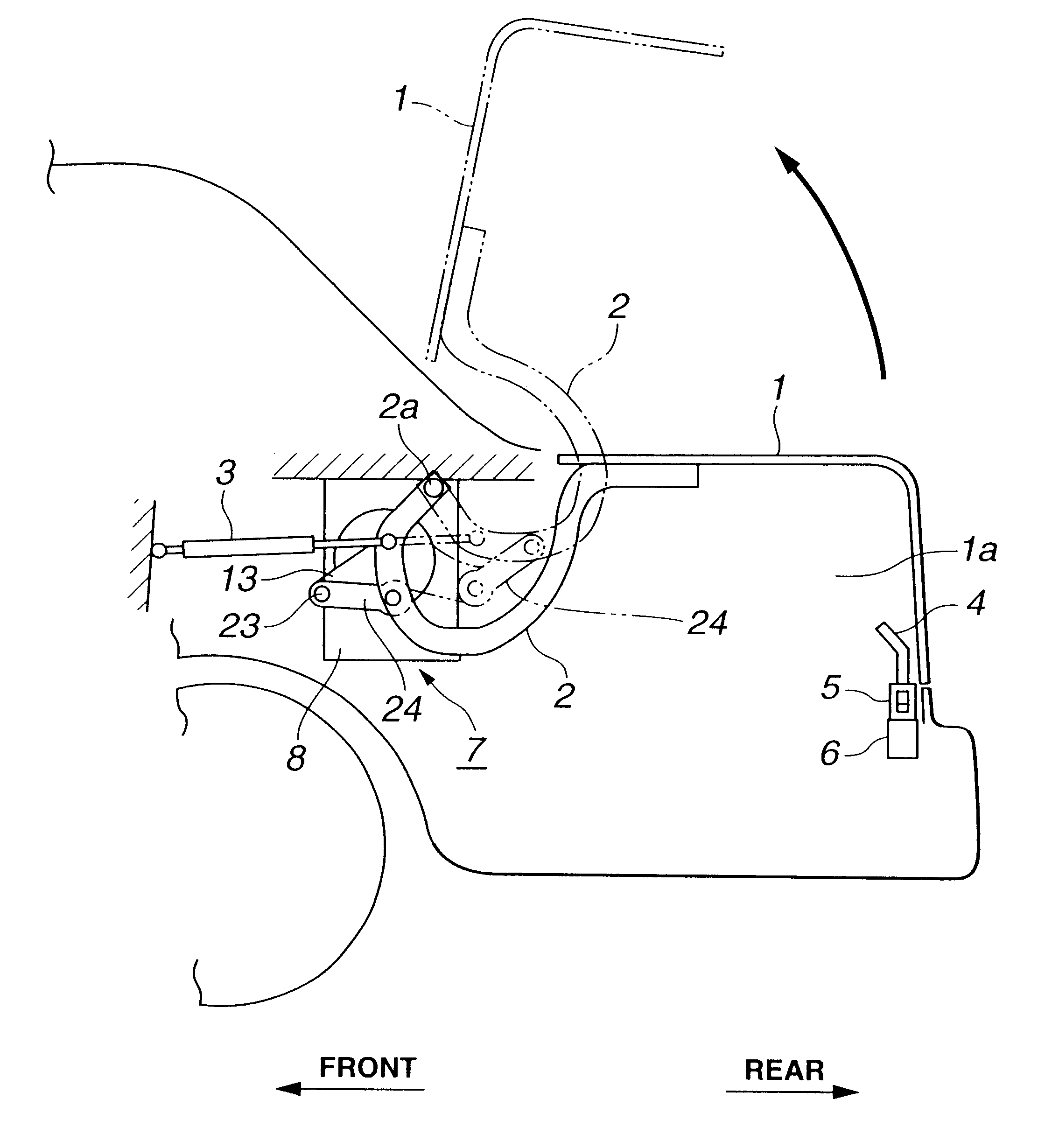
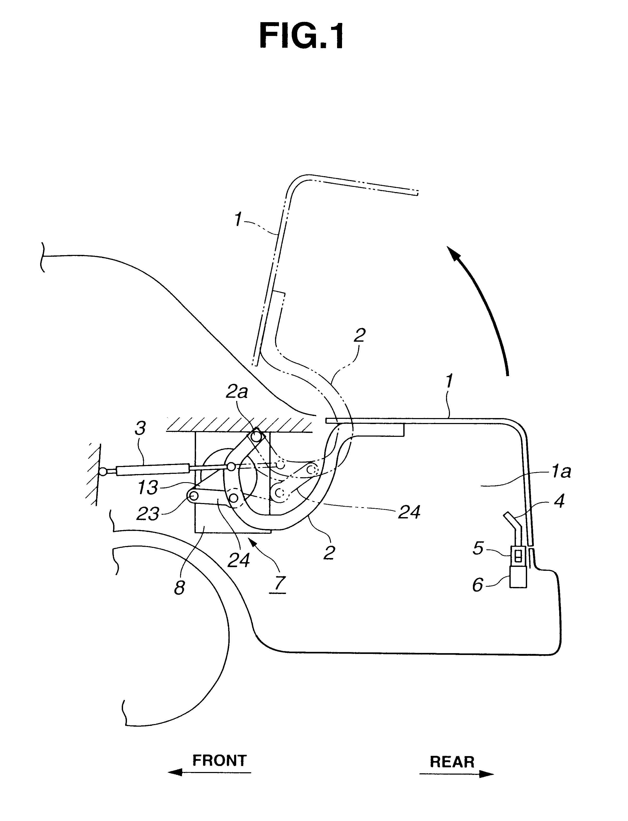
Referring to FIG. 1, there is shown a rear part of a motor vehicle to which a power unit 7 of the present invention is practically applied. As is shown in the drawing, the rear part of the vehicle has a pivotal trunk lid 1 to selectively close and open a trunk room 1a defined in the rear part. For the pivotal connection of the trunk lid 1 to the vehicle body, two curved hinge arms 2 are employed, which are positioned at laterally opposed portions of the trunk room 1a. The hinge arm 2 shown in the drawing is a left one that is positioned at a left side with respect to a travelling direction of the vehicle. Each hinge arm 2 has one end secured to the trunk lid 1 and the other end pivotally connected to the vehicle body through a hinge pin 2a. With this arrangement, the trunk lid 1 pivots between a full-closed position as shown by a solid line and a full-open position ...


PUM


Abstract

A base plate has mutually opposed first and second side surfaces. A first group of parts are arranged on the first side surface, which includes an electric motor, a speed reduction unit and an electromagnetic clutch. The speed reduction unit has a gear member which is projected to the second side surface from the first side surface through an opening formed in the base plate and driven by the motor when the electromagnetic clutch assumes ON condition. A second group of parts are arranged on the second side surface, which includes an intermediate gear which is rotatably connected to the base plate and meshed with the gear member, an output gear which is rotatably connected to the base plate through a shaft secured to the output gear and meshed with the intermediate gear and an output arm which is connected to the output gear to rotate therewith. The output arm is connected to the lid through a link.

Description

1. Field of the InventionThe present invention relates to power units for moving automotive movable members with the aid of electric power, and more particularly to power units of a type which moves an automotive trunk lid between open and closed positions with the aid of electric power.2. Description of Related ArtHitherto, various power units for automotive trunk lids have been proposed and put into practical use. One of them is shown in Laid-open Japanese Utility Model Application (Jikkai-sho) 63-117979. The power unit of this application is applied to a trunk lid which is pivotally connected to a vehicle body to open and close a trunk room defined in a rear part of the vehicle body. The power unit generally comprises an electric motor mounted on a panel in the trunk room, an output arm driven by the motor, a hinge arm fixed to the trunk lid and a link extending between the output arm and the hinge arm. That is, upon energization of the electric motor, the torque of the motor is ...

Claims


Application Information

Patent Timeline
Patent Type & Authority Patents(United States)
IPC IPC(8): B62D25/12B62D25/10E05F15/12
CPCB62D25/12E05F15/63E05Y2201/246E05Y2201/462E05Y2201/224E05Y2201/624E05Y2201/216E05Y2900/548
Inventor NAKAGOME, KATSUMI
Owner MITSUI KINZOKU ACT
Why Eureka
Try Eureka