Instrument or forceps for medical and particularly endoscopic applications

a technology of endoscopic instruments and forceps, which is applied in the field of endoscopic instruments, can solve the problems of unsatisfactory ergonomics of the operating unit so far used in the prior art, errors in the operation of the instrument, and inability to intuitively know the operating uni

Inactive Publication Date: 2003-08-12
KARL STORZ GMBH & CO KG
View PDF7 Cites 121 Cited by
  • Summary
  • Abstract
  • Description
  • Claims
  • Application Information

AI Technical Summary

Problems solved by technology

The operating units so far used in prior art are, however, unsatisfactory from an ergonomic point of view, especially when more than one distal functional element must be operated.
F...

Method used


Image

  • Instrument or forceps for medical and particularly endoscopic applications
  • Instrument or forceps for medical and particularly endoscopic applications
  • Instrument or forceps for medical and particularly endoscopic applications

Examples


first embodiment

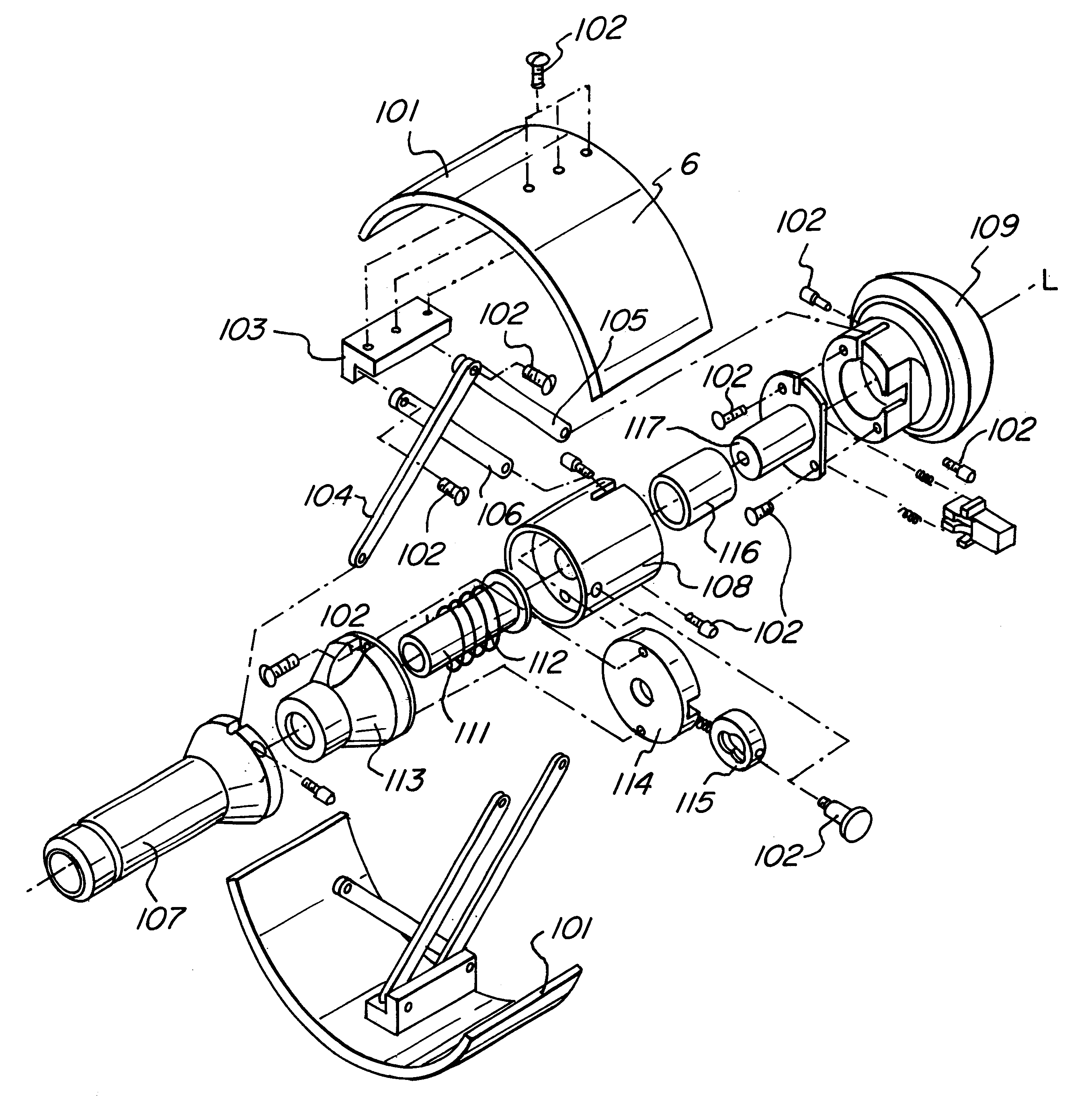
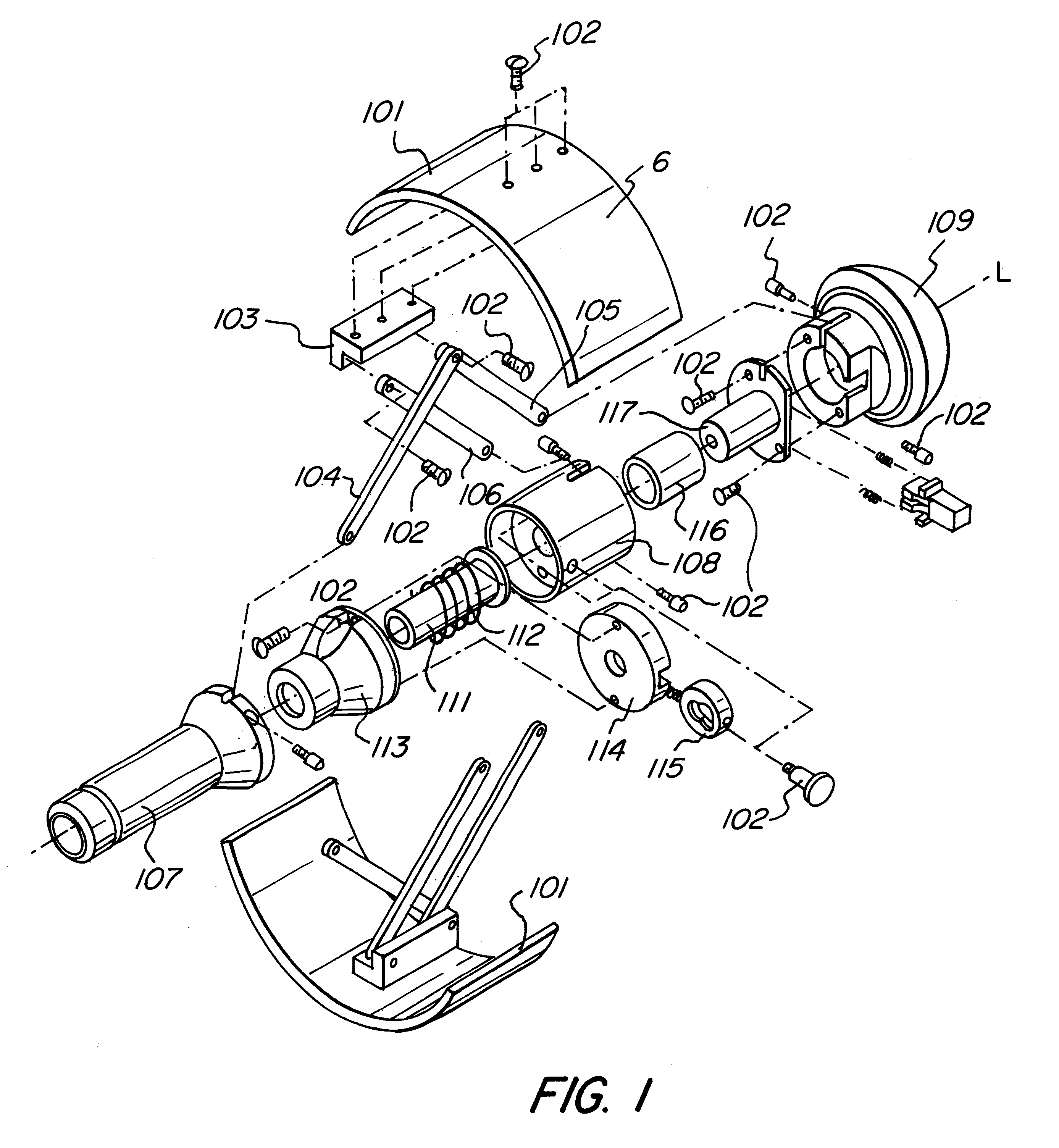
FIG. 1 is an exploded view of the operating unit of an inventive instrument. The distal portion, which may be designed in any form whatsoever and which is shown in FIG. 4 merely as an example, is not illustrated.

The operating unit comprises two elements, i.e., two semi-annular members 101 which are manipulatable (e.g., pivotable or tiltable) in a forward and rearward direction along the longitudinal axis L of the instrument and which are components of the surface of the operating unit. A fastening block 103 is mounted by means of screws 102 on each element 101, on which block a linkage is articulated, again by means of screws 102, which consists of a plurality of link elements, e.g., three rods 104, 105 and 106. Ergonomically adapted gripping depressions G, which are not illustrated in details, may be provided on the elements 101.

The rod 104 is articulated by its rear or proximal end (in the direction of the longitudinal axis L) of the fastening block 103, together with the rod 105,...

second embodiment

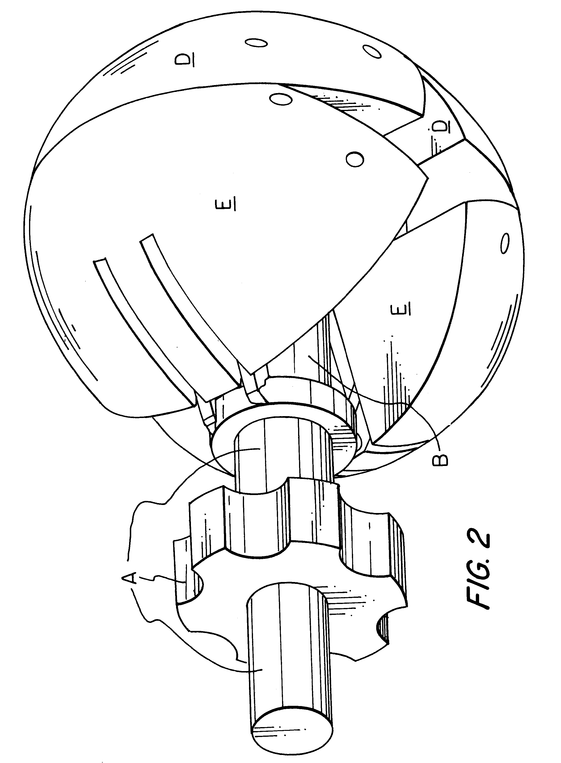
FIG. 2 is a perspective unit of the operating unit of a second embodiment, which can be used instead of the operating unit shown in FIG. 1. Moreover, this operating unit--in a simplified embodiment--is also suitable for instruments in which merely a distal functional element is actuated by shifting a rod in the connecting element.

The mode of operation of the second embodiment will now be explained with reference to the sectional views shown in FIGS. 3a-3c.

In this embodiment, too, the operating unit is the handle at the same time. The operating unit is taken by the operator's hand in such a way that it is enclosed by the hand and bears against the thenar by its proximal end.

In the illustrated second embodiment the operating unit has the shape of a sphere which is subdivided into four segments D, D, E and E whereof respectively two, i. e. the segments D and D or E and E are coupled to each other. The mutually coupled segments are provided in symmetry relative to a plane containing the...


PUM


Abstract

What is described here is an instrument for medical and particularly endoscopic applications, comprisinga proximally disposed operating unit,a distally disposed multi-part functional element having individual parts which are jointly and additionally independently movable, such as a multi-part forceps jaw, andan elongate connecting part which is disposed between the operating unit and said forceps jaw.The invention is characterized by the provisions that said operating unit is so configured that it can be grasped around by one hand, and that said operating unit comprises at least two pivotable and/or tiltable elements which are a component of the surface of said operating unit and which, when moving, control each one part of said multi-part functional element.

Description

The present invention relates to an instrument for medical applications, and particularly to an instrument for endoscopic applications which includes a multi-part functional element (for example, end effectors or forceps jaws) and an operating unit for the operation of the functional element for effecting a surgical operation.PRIOR ARTEndoscopic instruments such as forceps or pincers have become known wherein the jaws of the forceps is adapted to perform not only simple opening or closing movements, respectively, as this is the case with the forceps known from the document WO 94 / 20034. For an explanation of all details not described here in more details explicit reference is made, by the way, to that prior art document.For instance, the most different instruments are known which present two or more functional elements on their distal end, which can be pivoted or displaced along the longitudinal axis of the instrument and which are adapted to perform mutually independent movements an...

Claims


Application Information

Patent Timeline
IPC IPC(8): A61B17/28A61B17/32A61B17/00
CPCA61B17/2909A61B17/320016A61B2017/00353A61B2017/00424A61B2017/2919A61B2017/2926A61B2017/2938
Inventor CUSCHIERI, ALFREDFRANK, TIMOTHY GRAHAM
Owner KARL STORZ GMBH & CO KG
Why Eureka
Try Eureka