Footwear sole and arch strapping system

a sole and arch technology, applied in the field of soles and arch strapping systems, can solve the problems of ankle or instep straps, no prior art disclosure, and no other existing strapping configurations have been entirely satisfactory in securing footwear,

Inactive Publication Date: 2003-08-19
DECKERS OUTDOOR CORPORATION
View PDF31 Cites 68 Cited by
  • Summary
  • Abstract
  • Description
  • Claims
  • Application Information

AI Technical Summary

Problems solved by technology

None of these prior art disclosures, however, nor any other existing strapping configurations have been entirely satisfactory in securing footwear to the foot while maintaining a comfortable, durable, and convenient configuration.
This problem is particularly acute for sandals used in sports or other vigorous activities.
One particular problem relates to ankle or instep straps.
Without such compensation, the ankle strapping may overly restrict foot movement.
This causes discomfort in the user and diminishes the strength capacity of the strap.
Such straps cannot remain taut during activity, due to movement of other portions of the foot.
A continuous strap that covers both the instep and the forefoot, for instance, may lack the continuous, taut fit over the instep due to movement of the forefoot.
In addition to footwear strapping systems, other problems related to movement of the sole in relation to the foot also remain unresolved by the prior art.
In particular, difficulties are associated with providing torsional rigidity, arch support, and overall stiffness to a sole during walking, running, or other vigorous activity.
While a generally soft and cushioned sole forefoot and heel portion are desirable for wearer comfort, they may result in a sole being undesirably soft and "floppy".
Such prior art shanks do not, however, adequately prevent and generally, are not well-configured to counteract the twisting type of torsional forces developed during wearing of footwear, especially those forces caused by straps that pass through the sole.
Further, unresolved needs exist for an integral, stiff and rigid shank portion to provide torsional rigidity and stiffness to an otherwise relatively soft and cushioned footwear forefoot and heel portions.

Method used


Image

  • Footwear sole and arch strapping system
  • Footwear sole and arch strapping system
  • Footwear sole and arch strapping system

Examples


Embodiment Construction

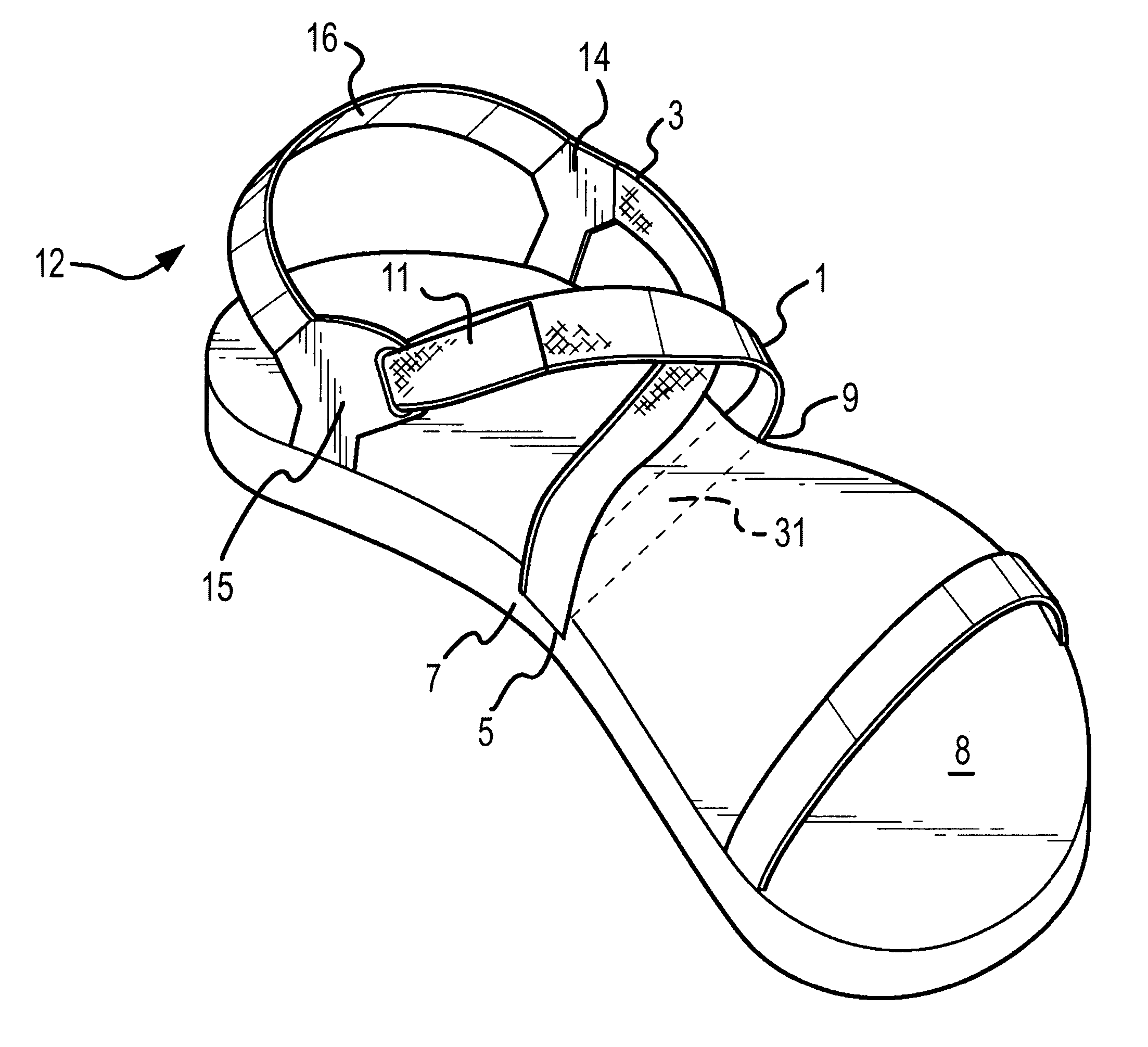
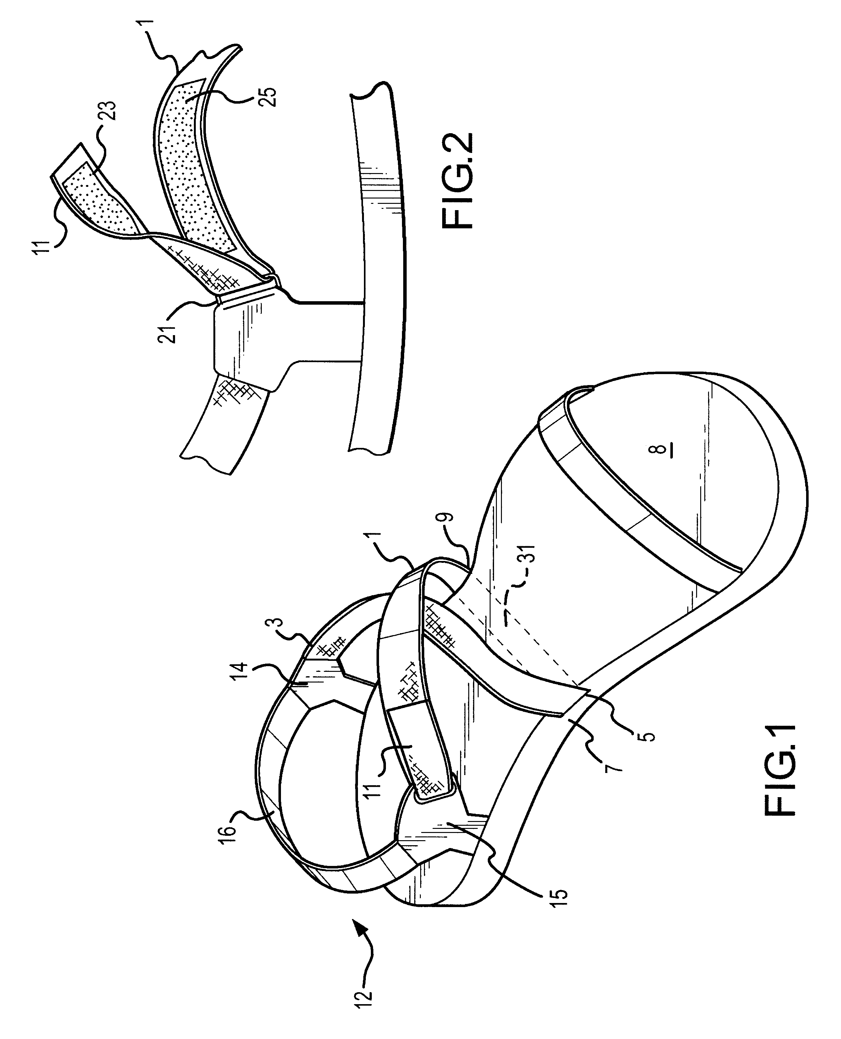
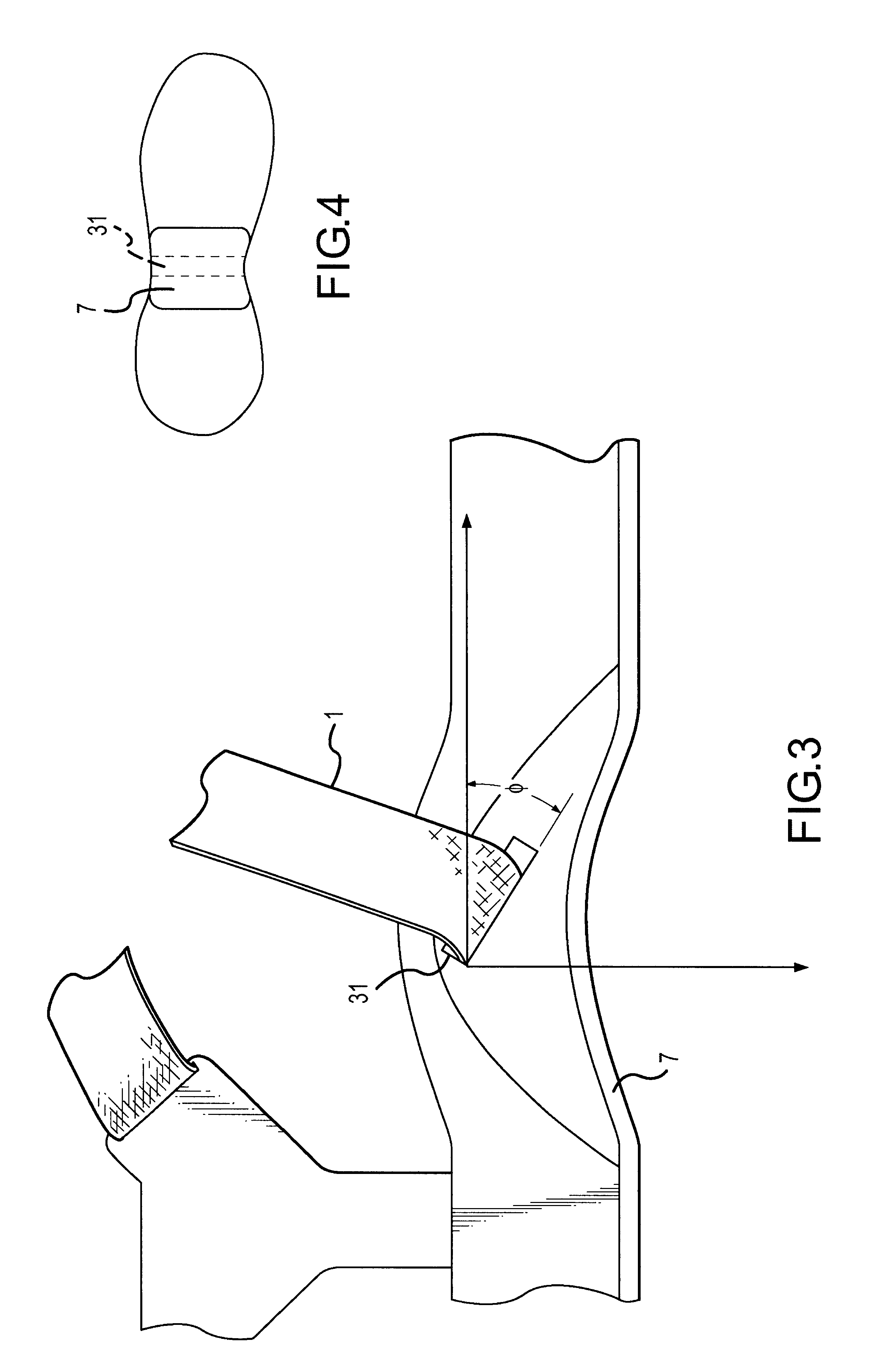
Turning now to the drawing figures, FIG. 1 is a perspective view of footwear showing one embodiment of the strapping system of the present invention. The footwear may be of any type, including sandals. The footwear, as is conventional, includes a forefoot and heel portions, with a midfoot portion therebetween. In accordance with certain aspects of the present invention, a channel 31 is provided through the midfoot portion of a sole of the footwear, underlying the user's arch, as more fully explained below.

Preferably, strap 1 is operatively attached at a first end 3 to one side, e.g. the lateral side, of the heel portion of the footwear. Strap 1 preferably extends transversely across and forwardly across and over the instep of a wearer's foot. In accordance with certain aspects of the present invention, a strap passes through midfoot channel 31, entering at a medial side 5 and emerging at a lateral side 9. Strap 1 then preferably extends in a rearward, transverse direction back acros...


PUM


Abstract

A strapping system for footwear comprises a strap (1) that has a first end (3) connected to a first side of a heel portion (12) of footwear, passes over the instep of a foot, through a channel (31) extending through the midfoot of the footwear sole and back over the foot instep to thereby forming an X shape over the wearer's foot. The strap (1) has a second end (11) which may be adjustably connected to the second side of a heel portion (12) of a sole. The channel (31) is resilient and rigid so as to allow the strap freedom of movement during use: thereby achieving a dynamic and self adjusting strap fit. A footwear sole comprises relatively soft forefoot and heel portions with a more rigid shank portion therebetween to provide the sole with stiffness and torsional rigidity.

Description

1. Field of the InventionThe present invention relates to footwear. In particular, the present invention is related to strapping systems for securely affixing footwear to a user's foot, and to shanks for providing rigidity and support to shoe soles.2. Background of the InventionThere is a wide variety of prior art showing strapping configurations for footwear. Generally, the purpose of such strapping may be summarized as securing the footwear to a user's foot and is often used in connection with sandals.Examples of prior art showing sandal or footwear strapping arrangements include U.S. Pat. Nos. 4,200,997 and 4,446,633 to Scheinhaus, U.S. Pat. No. 4,679,334 to McBride, U.S. Pat. No. 3,327,410 to Park, U.S. Pat. No. 4,793,075 to Thatcher, U.S. Pat. No. 4,817,302 to Saltsman, U.S. Pat. No. 4,300,294 Riecken, U.S. Pat. No. 2,788,591 to Gibson, U.S. Pat. No. 2,126,094 to Daniels, and U.S. Pat. No. 2,862,311 to Ellis. Each of these patents disclose strapping configurations which general...

Claims


Application Information

Patent Timeline
Patent Type & Authority Patents(United States)
IPC IPC(8): A43C11/14A43C11/00A43B3/12
CPCA43B3/126A43C11/1493
Inventor RITTER, BRETT D.BUTLER, DAMON R.MCGEOUGH, BARRY JOSEPHNORTON, EDWARD J.SMOTRYCZ, ZENON O.
Owner DECKERS OUTDOOR CORPORATION
Why Eureka
Try Eureka