Cup assembly with retaining mechanism

a technology of retaining mechanism and cup, which is applied in the direction of feeding bottles, transportation and packaging, drinking vessels, etc., can solve the problems of leaking liquid stored in the cup from the drinking spout and the air ven

Inactive Publication Date: 2003-08-19
PLAYTEX PROD INC
View PDF15 Cites 55 Cited by
  • Summary
  • Abstract
  • Description
  • Claims
  • Application Information

AI Technical Summary

Problems solved by technology

However, drinking spouts and air vents are liable to leak liquid stored in the cup between feedings, or if dropped during use.

Method used


Image

  • Cup assembly with retaining mechanism
  • Cup assembly with retaining mechanism
  • Cup assembly with retaining mechanism

Examples


Embodiment Construction

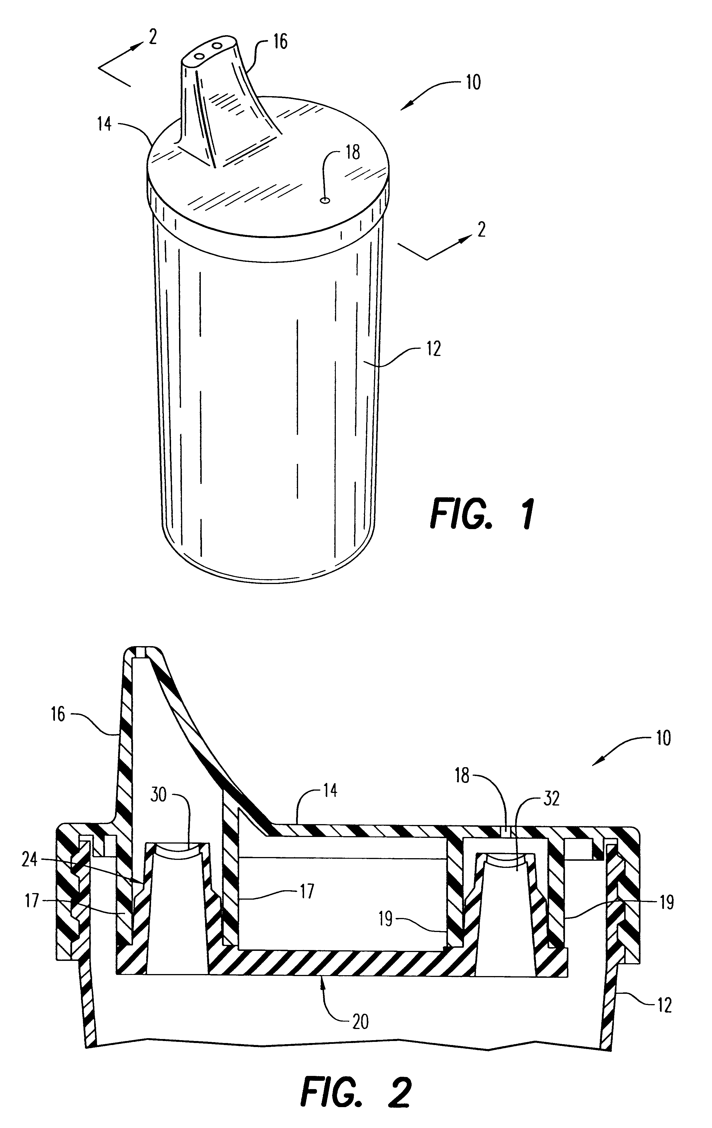
Referring to the figures and, in particular, FIG. 1, a cup is generally referred to by reference numeral 10. The cup 10 includes a container 12 and a cap or lid 14 that is adapted to seal cup 12. The cap or lid 14 has a spout 16 and an air vent 18 formed in its surface.

Referring to FIG. 2, lid 14 has, extending from the undersurface thereof, a first sleeve 17 and a second sleeve 19. The first sleeve 17 and second sleeve 19 are preferably cylindrical in shape. The first sleeve 17 aligns with spout 16, while second sleeve 19 aligns with air vent 18.

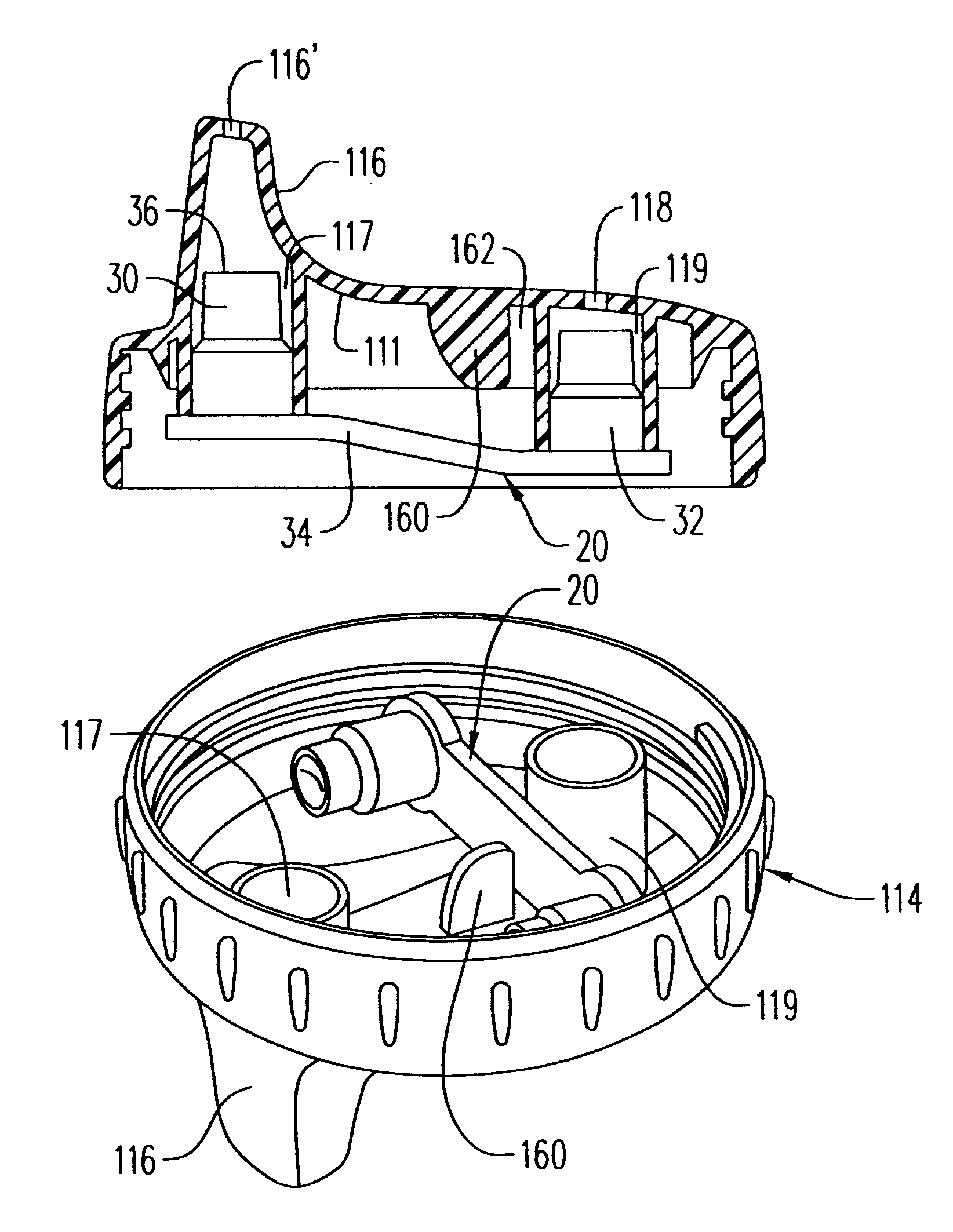
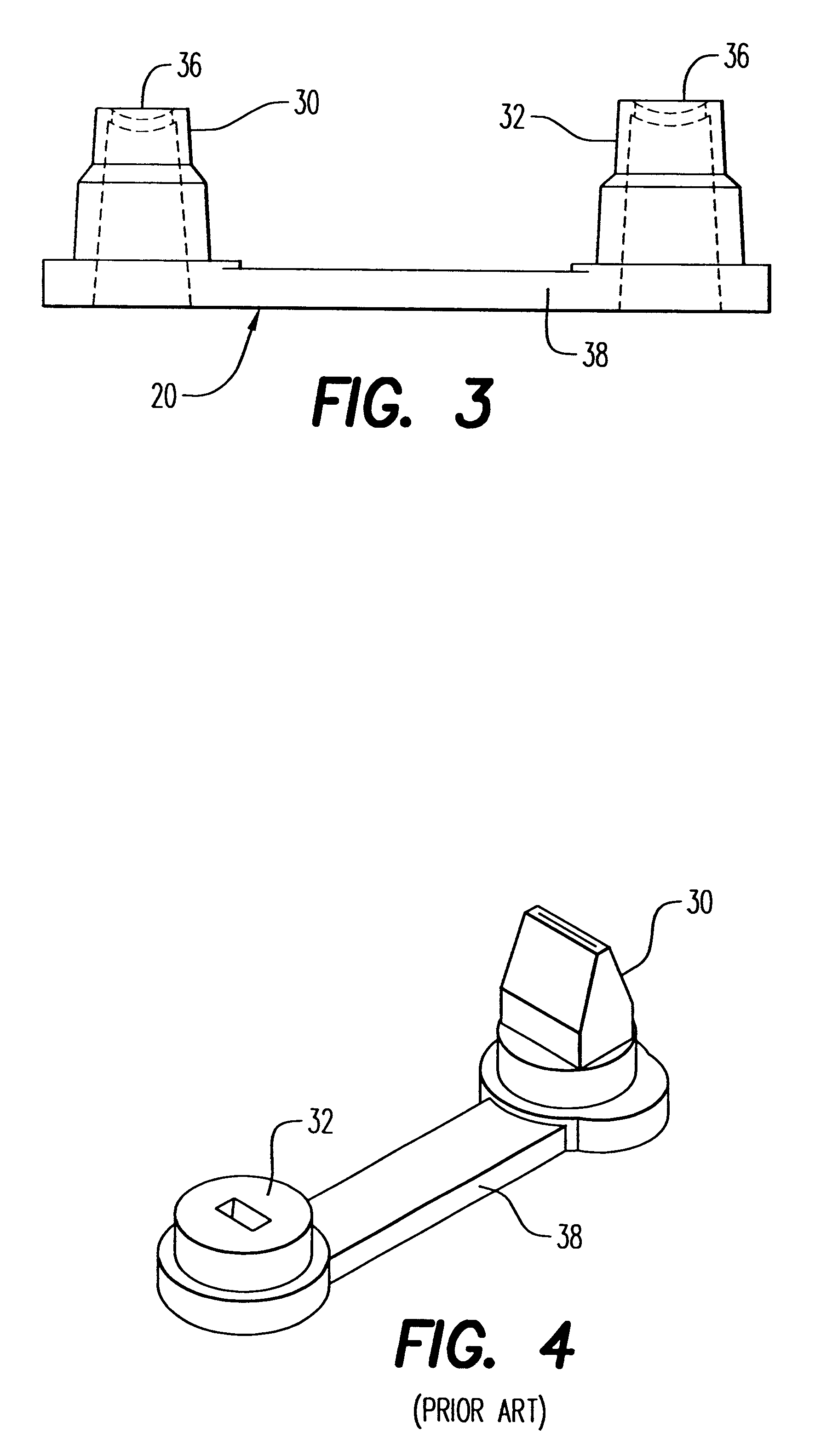
Referring to FIG. 3, flow control element or valve mechanism 20 has first valve portion or stack 30 and second valve portion or stack 32 connected together by substrate 34. Each valve portion 30, 32 has a lower portion 26, an upper portion 28 and valve faces 36 bearing slits. Each valve portion 30, 32 is configured, to frictionally engage first sleeve 17 and second sleeve 19, respectively, and place the flow control valve in fluid communica...


PUM


Abstract

A drinking cup assembly having a cup having an open end, a cap adapted to enclose the open end, the cap having a drinking spout and an air vent and a pair of mating surfaces that align with the drinking spout and the air vent, and a removable flow control valve adapted to engage the mating surfaces. The cap has a retaining mechanism that in conjunction with one mating surface secures in place the flow control element when not in use.

Description

1. Field of the InventionThe present invention relates generally to an improved leak-proof cup. More particularly, the present invention relates to a cup assembly having a drinking spout, an air vent spaced from the drinking spout, and a removable flow control element that engages in the vicinity of the drinking spout and air vent to control the flow of liquid and air from the drinking spout and the air vent. Moreover, the present invention provides a retaining mechanism to frictionally engage the flow control element when in a non-use or storage position.2. Description of the Prior ArtDrinking cups having one or more drinking spouts and a separate air vent. These cups allow the user to drink from the spout without creating excessive vacuum in the cup. However, drinking spouts and air vents are liable to leak liquid stored in the cup between feedings, or if dropped during use. Accordingly, certain drinking cups have been developed that use one or more removable flow control elements...

Claims


Application Information

Patent Timeline
Patent Type & Authority Patents(United States)
IPC IPC(8): A47G19/22B65D47/20B65D47/04B65D51/16A47G19/12B65D47/06B65D47/32
CPCA47G19/2272B65D47/2031B65D51/165
Inventor MANGANIELLO, FRANCIS XRANDOLPH, ROSS STEVEN
Owner PLAYTEX PROD INC
Why Eureka
Try Eureka