Pressure actuated flow control valve

a technology of flow control valve and pressure actuator, which is applied in the direction of valves, intravenous devices, other medical devices, etc., to achieve the effect of reducing the cross-sectional thickness of the dome and reducing the total apical deflection

Inactive Publication Date: 2005-01-13
DIKEMAN W CARY +1
View PDF25 Cites 129 Cited by
  • Summary
  • Abstract
  • Description
  • Claims
  • Application Information

AI Technical Summary

Benefits of technology

[0017] The present invention is directed to a pressure actuated flow control valve for an infusion catheter which permits gravity flow of a liquid through the catheter and into a patient while resisting back flow of blood from the patient and into the catheter. The valve is a flexible unitary body having a central wall that defines a fluid passageway portal. The valve includes a central wall, which in one embodiment is a hemispherical dome-shaped body having concave inner and convex outer surfaces. However, dome-shaped as utilized herein does not necessarily mean that the concave inner and the convex outer surfaces are spherical or substantially spherical. Dome-shaped simply refers to the concave and convex nature of the surfaces in that they have an arcuate cross-section but not necessarily circular. A normally closed opening communicates between the surfaces. The opening, normally identified as a slit, can extend along a diameter of the central wall and is configured so that it is longer on the convex outer surface than on the concave inner surface. The term slit is utilized to refer to a narrow elongated opening or cut such that the

Problems solved by technology

However, dome-shaped as utilized herein does not necessarily mean that the conca

Method used


Image

  • Pressure actuated flow control valve
  • Pressure actuated flow control valve
  • Pressure actuated flow control valve

Examples


Embodiment Construction

[0034] As required, detailed embodiments of the present invention are disclosed herein; however, it is to be understood that the disclosed embodiments are merely exemplary of the invention, which may be embodied in various forms. Therefore, specific structural and functional details disclosed herein are not to be interpreted as limiting, but merely as a basis for the claims and as a representative basis for teaching one skilled in the art to variously employ the present invention in virtually any appropriately detailed structure.

[0035] Certain terminology will be used in the following description for convenience in reference only and will not be limiting. For example, the words “distally” and “proximally” will refer to directions respectively toward and away from a patient.

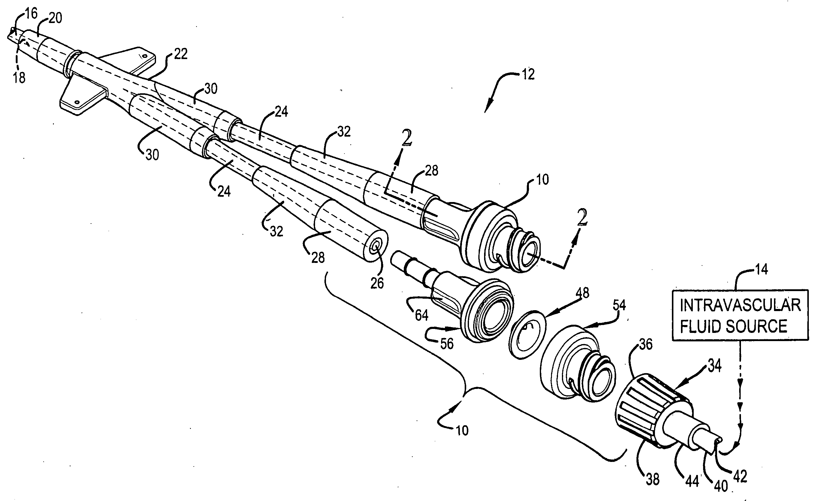
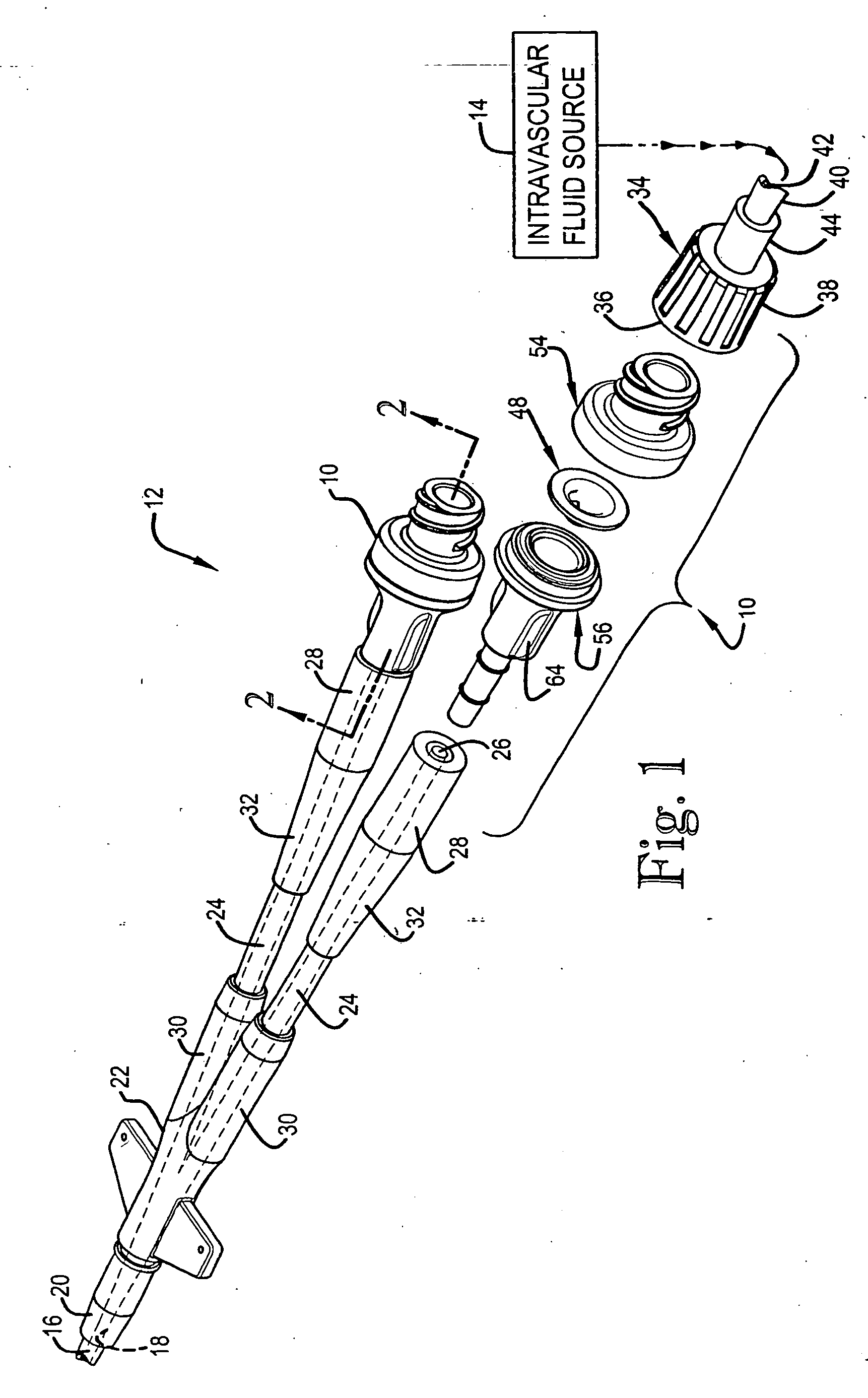
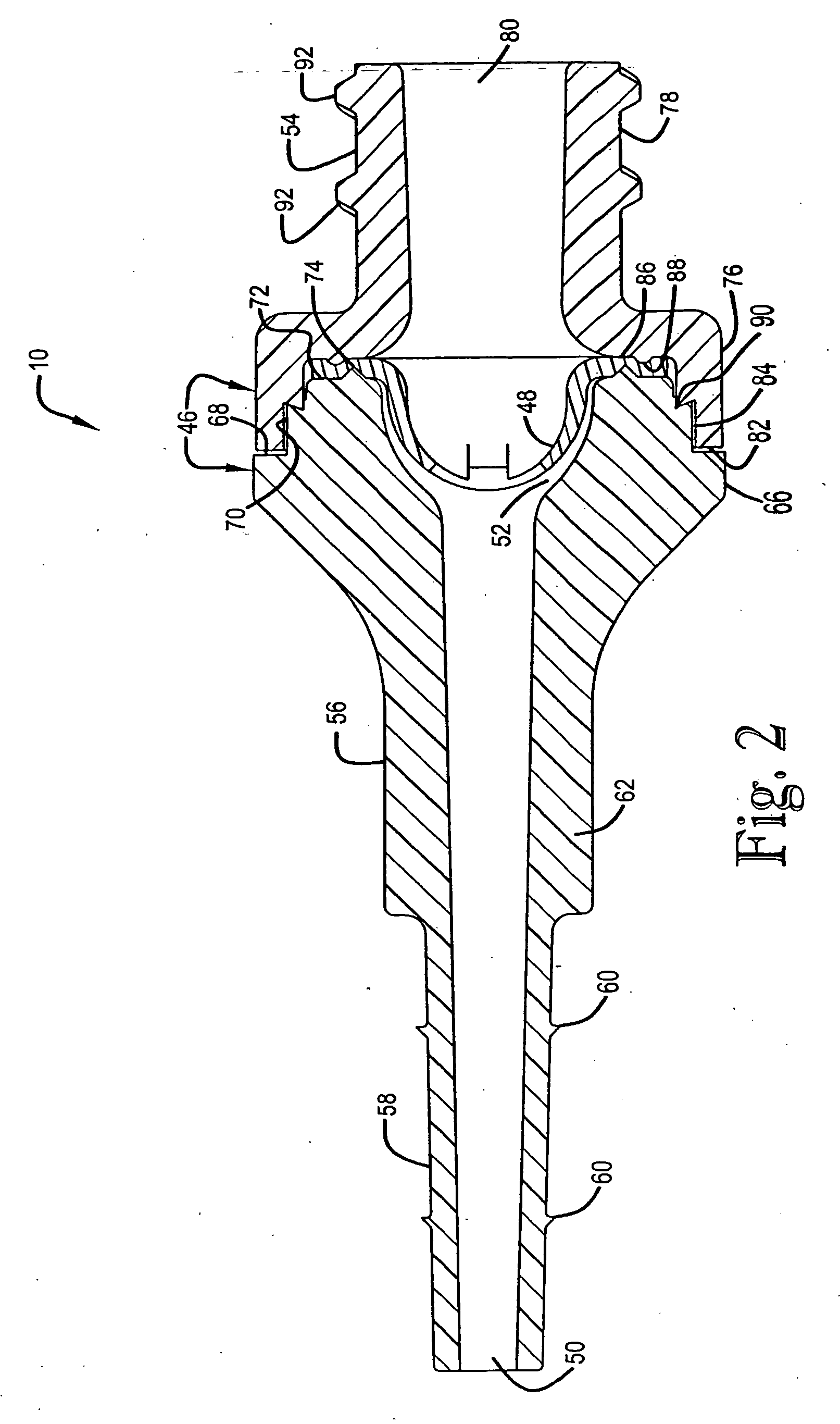
[0036] Referring now to the drawings, a pressure actuated flow control valve assembly in accordance with the invention is generally indicated by the reference numeral 10 and is depicted in FIGS. 1 and 2. FIG. 1 ...


PUM


Abstract

A pressure actuated flow control valve for an infusion catheter permits gravity flow of a liquid through the catheter and into a patient while resisting back flow of blood from the patient and into the catheter. The valve has a hemispherical body with an outstanding circumferential flange and a normally closed, diametric slit. The slit is longer on the convex outer surface than on the concave inner surface. Dome thickness diminishes in the area adjacent the slit, reducing total apical deflection upon collapse of the slit toward the concave surface. An inner orthogonal rib biases the slit closed. Upon application of a predetermined pressure, the slit opens toward the concave surface to permit forward fluid flow. At lower pressures, the slit closes to check fluid flow. Greater reverse pressure is required to collapse the slit toward the concave surface to permit reverse fluid flow.

Description

CROSS REFERENCE(S) [0001] This application is a continuation-in-part application of U.S. application Ser. No. 10 / 304,833 filed Nov. 26, 2002BACKGROUND OF THE INVENTION [0002] 1. Field of Invention [0003] The present invention is broadly concerned with a control valve for a medical fluid infusion device. More particularly, it is concerned with a positive pressure actuated flow control valve that permits flow of a liquid from a reservoir, through a cannula and into a patient, while resisting reflux. [0004] 2. Background Art [0005] Medical infusion therapy employs peripheral and central intravascular devices such as venous and arterial catheters as well as peripherally inserted central venous catheters to deliver fluids, blood products, and pharmaceuticals, including antibiotics and biologics as well as parenteral nutrition. Intravascular devices may also be coupled with pressure monitoring systems. [0006] Regardless of the location of the insertion site of the catheter or the placemen...

Claims


Application Information

Patent Timeline
IPC IPC(8): A61M39/10A61M39/24
CPCA61M39/1011A61M2039/2426A61M2039/242A61M39/24
Inventor DIKEMAN, W. CARYSPIKER, KENY
Owner DIKEMAN W CARY
Why Eureka
Try Eureka