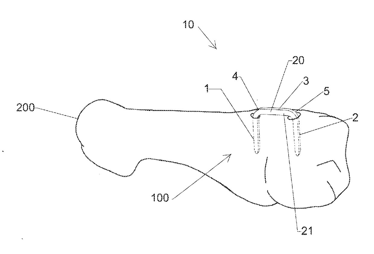
Elastic orthopedic implant and method of manufacturing thereof
a technology of orthopedic implants and implants, applied in the field of orthopaedic implants, can solve the problems of increasing the cost of etching implants after manufacture, not creating any lasting compression of the two bones, and causing bulges or protuberances, so as to achieve less protuberance to the patient, more smooth composite surfaces, and greater bending strength
- Summary
- Abstract
- Description
- Claims
- Application Information
AI Technical Summary
Benefits of technology
Problems solved by technology
Method used
Image
Examples
first embodiment
[0063]The bridge 205 includes a first upper section 230 and a second lower section 231. The first upper section 230 is the portion of the bridge 205 that lies above a plane 232 and the second lower section 231 is the portion of the bridge 205 that lies below the plane 232. The first upper section 230 includes a central surface 233 and first, second, third, and fourth surfaces 225-228. The central surface 233 may be linear to lower the profile of the first upper section 230. Alternatively, the central surface 233 may be non-linear to provide a smooth transition from the central surface 233 to each of the first, second, third, and fourth surfaces 225-228. The first surface 725 is non-linear and tapers from the central surface 233 to a first end transition 234 between the first upper section 230 and the second lower section 231. The second surface 226 is non-linear and tapers from the central surface 233 to a second end transition 235 between the first upper section 230 and the second ...
second embodiment
[0086]FIG. 28 illustrates an implant 1000 according to a The implant 1000 is shown in a converging position 1150. The implant 1000 includes legs 1001 and 1002 connected by a bridge 1005. The implant 1000 is a two-legged version of implant 210 such that the legs 1001 and 1002 are substantially identical to the legs 201 and 204 of the implant 210 and the bridge 1005 is substantially identical to the bridge 205. The bridge 1005 includes a first upper section 1115, which is substantially identical to the first upper section 230, and a second lower section 1116, which is substantially identical to the second lower section 231. The first upper section 1115 includes a central surface 1117 and first, second, third, and fourth surfaces 1006-1009, which are substantially identical the central surface 233 and the first, second, third, and fourth surfaces 225-228. The second lower section 1116 includes a central surface 1010 and first and second surfaces 1011 and 1012, which are substantially ...
third embodiment
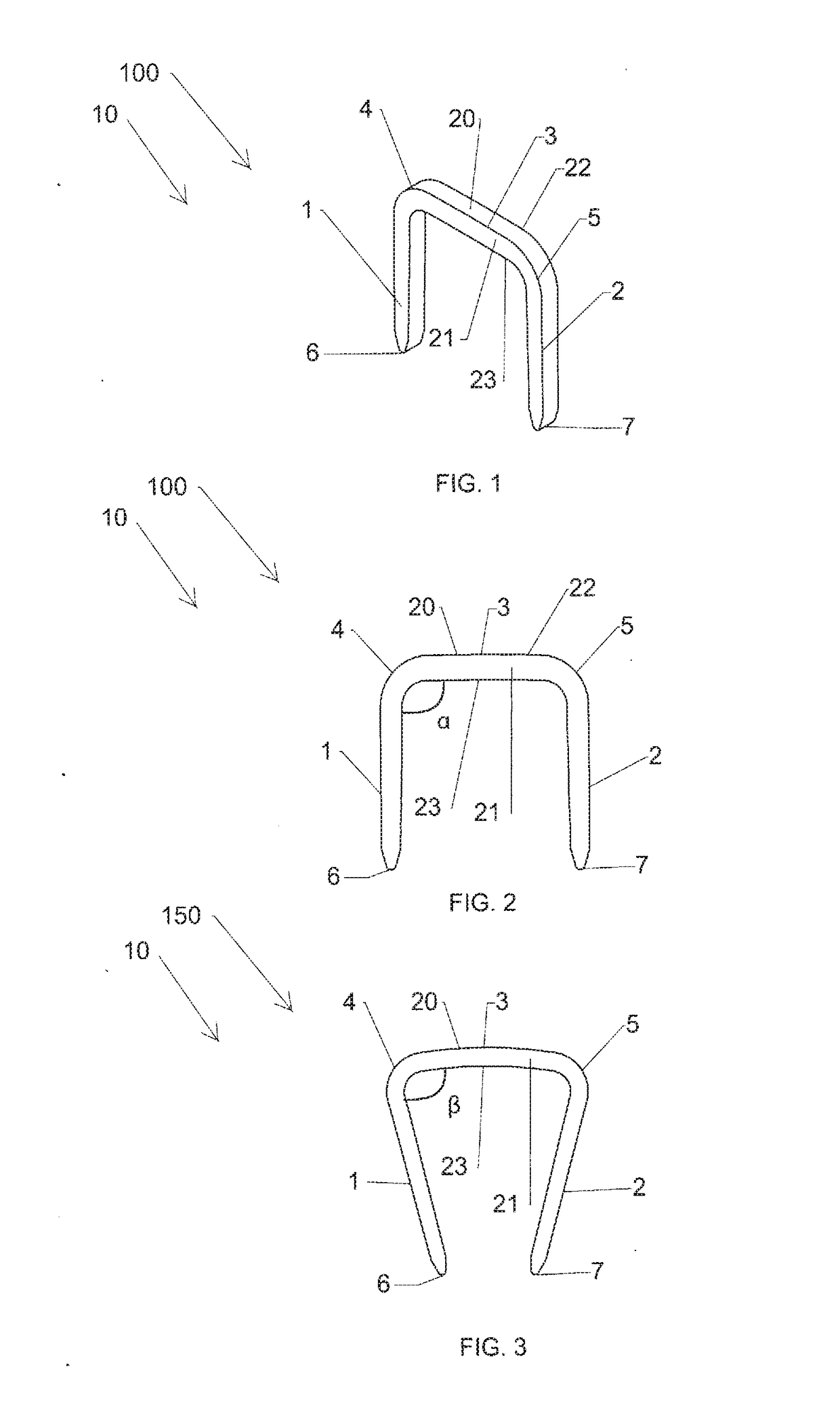
[0093]In the third embodiment, the first, second, third, and fourth surfaces 881-884 each taper from the central surface 880 at an angle of between 5 degrees and 85 degrees when measured from a plane tangent to the central surface 880. The tapering of the first, second, third, and fourth surfaces 881-884 from the central surface 880 provides the implant 810 with a second lower section 831 that has a smooth composite surface and a non-uniform cross-sectional thickness between the first, second, third, and fourth leg transitions 893-896 as illustrated in FIGS. 34-36 and 38-40. As a result, the implant 810 includes a low profile and provides less of protuberance to a patient.
[0094]FIG. 31 illustrates the implant 810 in the converging position 950 and with barbs on legs 801-804. In the converging position 950, each of the legs 801-804 has an acute angle of less than 90 degrees relative to the bridge 805. The implant 810 also has an insertion position that allows the implant 810 to be in...
PUM
| Property | Measurement | Unit |
|---|---|---|
| angle alpha | aaaaa | aaaaa |
| angle | aaaaa | aaaaa |
| angle | aaaaa | aaaaa |
Abstract
Description
Claims
Application Information
 - R&D
- Intellectual Property
- Life Sciences
- Materials
- Tech Scout
- Unparalleled Data Quality
- Higher Quality Content
- 60% Fewer Hallucinations
Browse by: Latest US Patents, China's latest patents, Technical Efficacy Thesaurus, Application Domain, Technology Topic, Popular Technical Reports.
© 2025 PatSnap. All rights reserved.Legal|Privacy policy|Modern Slavery Act Transparency Statement|Sitemap|About US| Contact US: help@patsnap.com


