Twin sheet pallet

a twin-sheet pallet and pallet technology, applied in the field of shipping and storage pallets, can solve the problems of twin-sheet pallets slipping or sag, sheet pallets failing to make provision to prevent pallet tipping, and difficulty in moving pallets over irregular transfer surfaces and over various transfer devices such as conveyors, so as to facilitate the movement of pallets, facilitate the firm positive receipt, and discourage tipping.

Active Publication Date: 2006-04-13
SHUERT TECH
View PDF11 Cites 42 Cited by
  • Summary
  • Abstract
  • Description
  • Claims
  • Application Information

AI Technical Summary

Benefits of technology

[0009] According to a further feature of the invention, each downwardly opening groove in the lower sheet is defined in part by a top wall; a series of upstanding knobs is provided on each groove top wall; the protrusions in the upper sheet are arranged in longitudinally extending rows; and portions of the top wall of the upper sheet between the rows are fused to the knobs. This specific arrangement provides a sturdy, simple twin sheet construction between the upper and lower sheets.
[0010] According to a further feature of the invention, laterally aligned slots are provided in sidewalls of the grooves and the protrusions to allow passage of the forks of a fork lift truck. This arrangement provides firm receipt of the forks of a forklift truck to discourage tipping.
[0011] According to a further feature of the invention, two longitudinally spaced protrusions are provided in each upwardly opening groove to provide longitudinally spaced laterally aligned sets of protuberances, and laterally aligned slots are provided in each set of protrusions and in the associated upstanding walls of the upwardly opening grooves and the downwardly opening grooves. This specific construction further facilitates the firm positive receipt of the two forks of the forklift truck.
[0012] According to a further feature of the invention, the lower sheet includes generally parallel upstanding side walls, generally parallel upstanding end walls, and a plurality of separate, flat, laterally spaced, parallel bottom walls extending from end wall to end wall, and the underfaces of the bottom walls define a pallet footprint comprised solely of a plurality of separate, flat, laterally spaced, parallel surfaces extending from end wall to end wall of the sheet. This specific construction further facilitates the movement of the pallet over transfer surfaces or transfer devices.
[0013] According to a further feature of the invention, the pallet further includes at least one metallic beam positioned between the upper and lower sheets and extending substantially from end wall to end wall of a pallet. This beam construction augments the bending strength to the pallet.
[0014] According to a further feature of the invention, the spacer knobs are arranged in laterally spaced longitudinally extending rows and the metallic beam is positioned between a top wall section of the lower sheet and a portion of the top wall of the upper sheet and extends substantially from end to end of the pallet between adjacent spacer knob rows. This arrangement allows the spacer knobs to further function to locate and retain the metallic beam.

Problems solved by technology

Whereas twin sheet pallets have in general proven to be superior to the wooden pallets previously in use, the undersurfaces of the pallets tend to be irregular so that movement of the pallets over irregular transfer surfaces and over various transfer devices such as conveyors is difficult and sometimes impossible.
Further, the prior art twin sheet pallets fail to make provision to preclude tipping of the pallet off of the forks of a forklift truck in the presence of an unbalanced load on the pallet.
Further, the prior art twin sheet pallets have tended to creep or sag after extended periods of use.

Method used


Image

  • Twin sheet pallet
  • Twin sheet pallet
  • Twin sheet pallet

Examples


Embodiment Construction

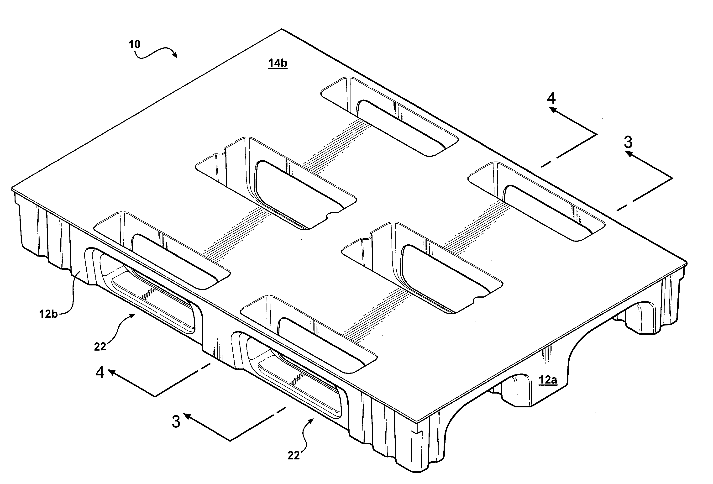
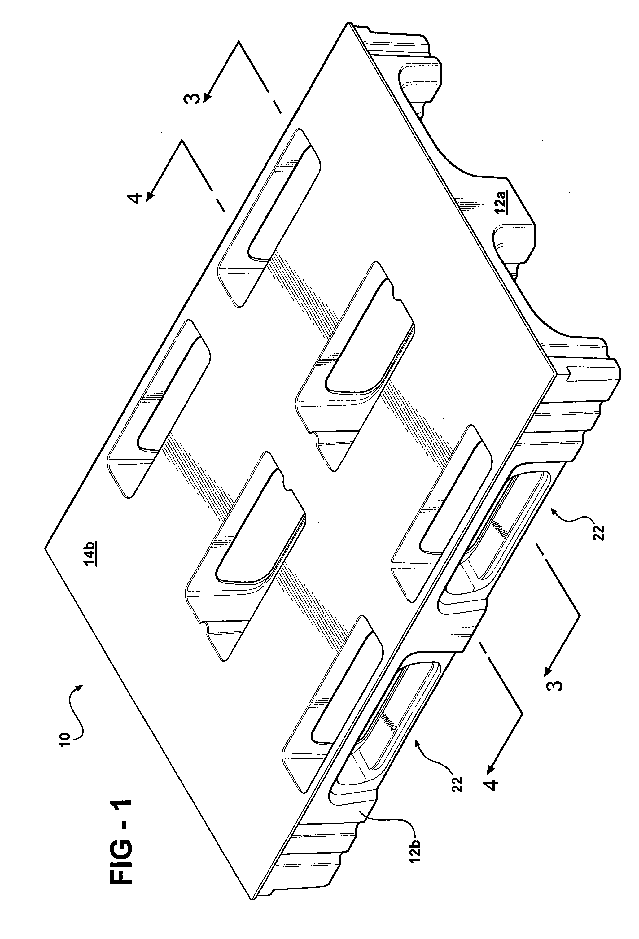
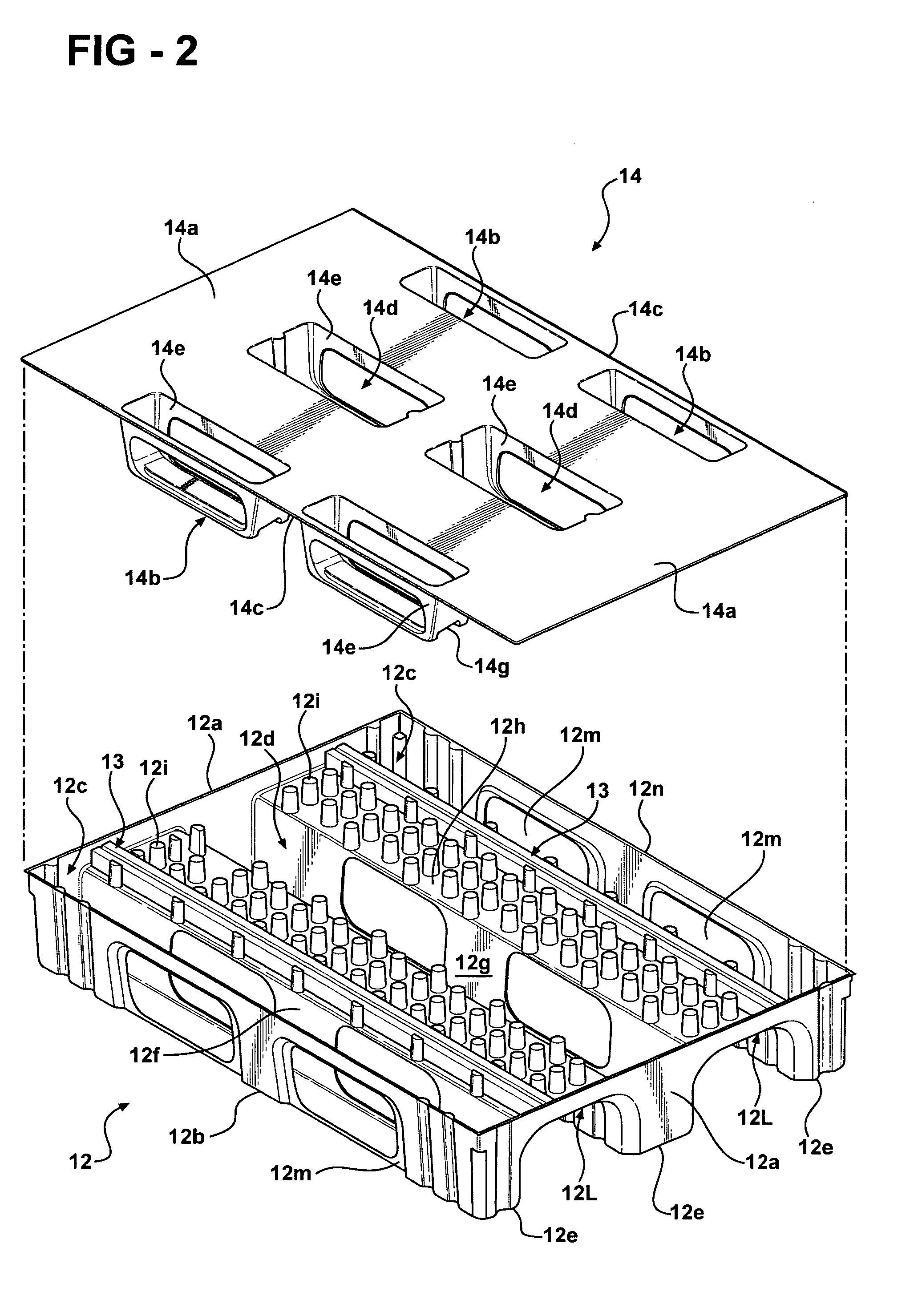
[0033] In overview, the invention pallet 10 is formed of lower and upper plastic sheets 12 and 14, knitted or fused together, and a pair of reinforcing steel beams 13 positioned between the upper and lower sheets.

[0034] Sheets 12 and 14 may be separately molded in a vacuum forming process, may be formed of an organic polymeric material such as polyethylene, and may be knitted or fused together to form the pallet in a compression molding process. The molds for vacuum forming the sheets are not shown but may be constructed in accordance with known vacuum forming techniques.

[0035] Each of the upper and lower sheets is formed from a generally rectangular planar plastic sheet and the sheets are fused together utilizing the molds while the sheets are in a heated, moldable state so that fusion may occur between the upper and lower sheets at any point where an interface is defined between the upper and lower sheets.

[0036] Lower sheet 12 starts out as a generally rectangular sheet of poly...


PUM


Abstract

A twin sheet plastic pallet comprising an upper plastic sheet and a lower plastic sheet selectively fused to the upper sheet. The lower sheet has a generally rectangular configuration, including sidewalls and end walls, and includes a plurality of separate parallel upwardly opening longitudinally extending U-shaped grooves extending from end to end of the sheet and a plurality of downwardly opening U-shaped grooves interspersed between the upwardly opening grooves and opening in the end walls of the sheet. The upper sheet defines a top wall, defining the platform surface of the pallet, and a plurality of upwardly opening U-shaped protrusions extending downwardly from the top wall and sized to nest within the upwardly opening grooves of the lower sheet, whereby with the upper sheet positioned over the lower sheet and the protrusions positioned in the upwardly opening grooves, the sheets may be fused together to form double thickness U-shaped wall structures at the interfaces of the protrusions and the upwardly opening grooves. The pallet further includes a pair of longitudinally extending metallic beams positioned between the upper and lower sheets, and laterally aligned slots are formed in the U-shaped wall structures to allow passage of the forks of a forklift truck.

Description

RELATED APPLICATION [0001] This application claims the priority of U.S. Provisional Patent Application Ser. No. 60 / 616,825 filed on Oct. 7, 2004.BACKGROUND OF THE INVENTION [0002] This invention relates to shipping and storage pallets and more particularly to plastic pallets embodying a twin sheet construction. [0003] Whereas twin sheet pallets have in general proven to be superior to the wooden pallets previously in use, the undersurfaces of the pallets tend to be irregular so that movement of the pallets over irregular transfer surfaces and over various transfer devices such as conveyors is difficult and sometimes impossible. Further, the prior art twin sheet pallets fail to make provision to preclude tipping of the pallet off of the forks of a forklift truck in the presence of an unbalanced load on the pallet. Further, the prior art twin sheet pallets have tended to creep or sag after extended periods of use. SUMMARY OF THE INVENTION [0004] This invention is directed to the provi...

Claims


Application Information

Patent Timeline
Patent Type & Authority Applications(United States)
IPC IPC(8): B65D19/38
CPCB65D19/0016B65D2519/00034B65D2519/00069B65D2519/00129B65D2519/00273B65D2519/00288B65D2519/00308B65D2519/00318B65D2519/00333B65D2519/00432B65D2519/00562B65D2519/00567B65D19/0038
Inventor SHUERT, LYLE H.
Owner SHUERT TECH
Why Eureka
Try Eureka