Gate section and base for a safety rail system

Inactive Publication Date: 2005-01-25
TRACTEL INC
View PDF4 Cites 29 Cited by
  • Summary
  • Abstract
  • Description
  • Claims
  • Application Information

AI Technical Summary

Benefits of technology

The general purpose of the present invention is to provide an improved gate section and an improved cast iron base for a safety rail system which is intended to be used to cordon off work areas and the like where human safety is an issue. When the cast iron base is coupled to the rail and/or gate sections, it has enough weight, mass and strength to withs

Problems solved by technology

One hazard is a potential tip-over of a forklift driving over the protrusions.
Another potential hazard is human injury should someone trip over the protrusions and fall.
These protrusions also become a nuisance when toe boards are not in use.
Also, the prior art bases have cutouts creating handle

Method used


Image

  • Gate section and base for a safety rail system
  • Gate section and base for a safety rail system
  • Gate section and base for a safety rail system

Examples


Embodiment Construction

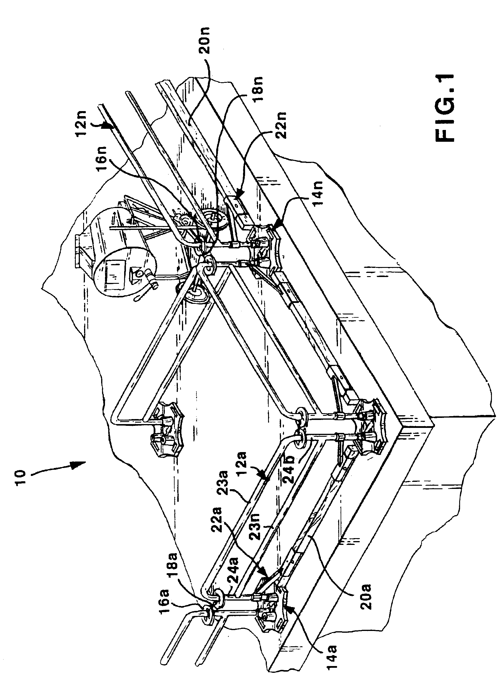
FIG. 1 illustrates a perspective view of a safety rail system 10. This illustration shows the safety rail system 10 assembled on a rooftop in a random configuration. The safety rail system 10 is comprised of a plurality of rail sections 12a-12n, a plurality of bases 14a-14n, a plurality of rail lock donuts 16a-16n, a plurality of securing chains 18a-18n, and a plurality of toe boards 20a-20n used in conjunction with a plurality of toe board receivers 22a-22n. Each component will be later described in detail with reference to the following figures.

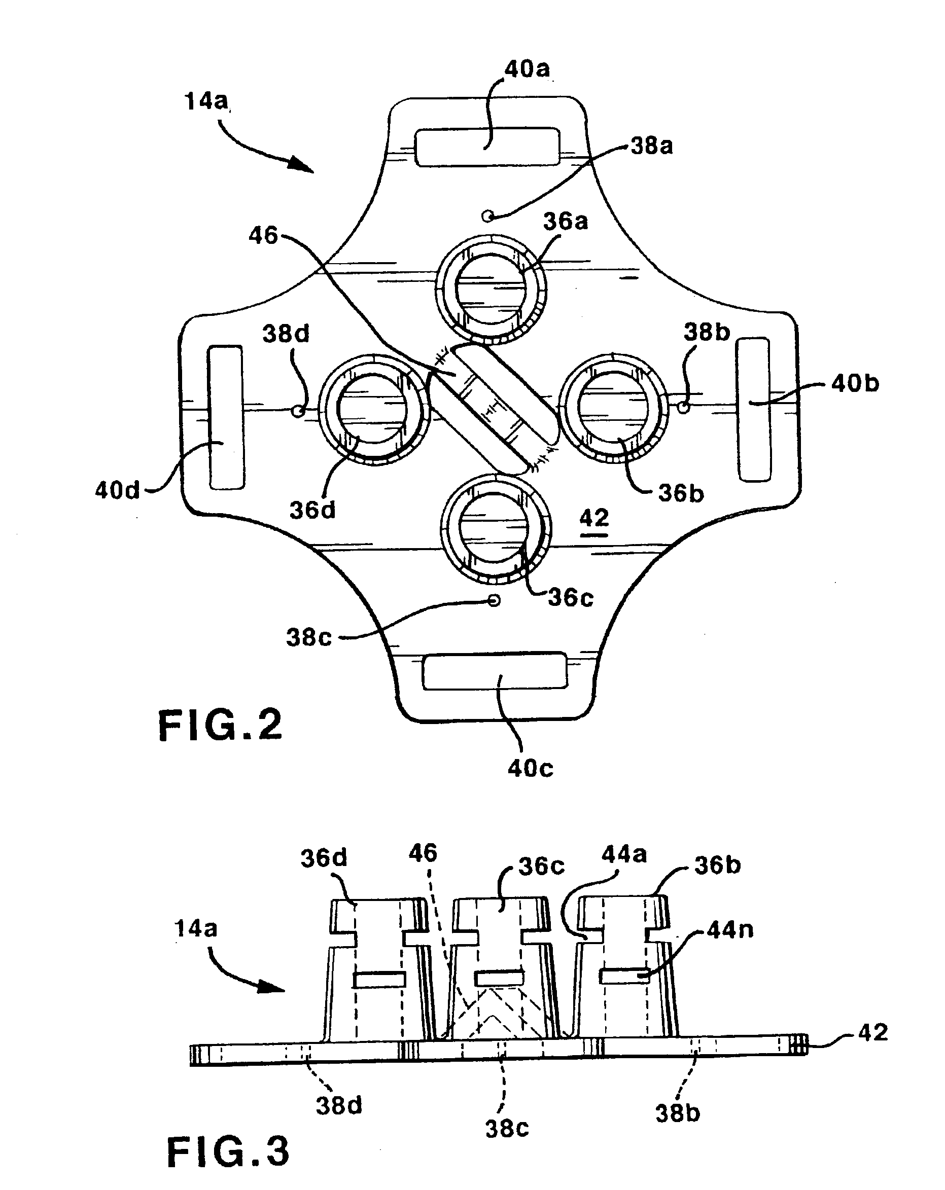
FIG. 2 illustrates a top view of a base 14a, and FIG. 3 illustrates a side view of base 14a. The bases 14a-14n weigh between 100-120 lbs. and are cast iron or welded plate and tube to support rail sections 12a-12n without tipping. Each base 14a-14n is constructed in the same manner having identical parts including a planar portion 42 with cutouts 40a-40d on four opposing sides creating built-in handles for transporting it. There is also a c...


PUM


Abstract

An improved gate section and base for a portable safety rail system which utilizes cast iron bases and hinged gate sections. The improved base includes four post receivers, recessed handles with smooth edges, and stacking recesses. The improved gate section incorporates a single pull double latching mechanism which includes two durable and robust latches each with its own manual operating tab but also a manual operating handle whereby both latches can be operated simultaneously.

Description

BACKGROUND OF THE INVENTION1. Field of the InventionThis invention pertains to a gate section and base for a safety rail system for providing a protective barrier for blocking access to a hazardous area or for preventing falls from an elevated area.2. Description of the Prior ArtPrior art safety rail systems required the user to secure components of the systems by some type of securing method, such as by using anchor bolts or by welding pieces together. One similar prior art system to that disclosed herein utilizes cast iron bases and rail sections. That system uses two post receivers on each cast iron base to support only two rail sections. In each post receiver are four cast holes spaced 90 degrees from one another. These holes are used to secure the rail sections to the base with some type of securing pin. In contrast, the base constructed in accordance with the present invention includes four post receivers each having a plurality of slots instead of holes to provide for infinit...

Claims


Application Information

Patent Timeline
IPC IPC(8): E04G21/32E04H17/16E04H17/18E04F11/18
CPCE04H17/18E04G21/3233E04G21/3238
Inventor KENTON, GREGORY S.
Owner TRACTEL INC
Why Eureka
Try Eureka