Optionally transferable optical system with a reduced thickness

Active Publication Date: 2014-12-25
VISUAL PHYSICS LLC (US)
View PDF12 Cites 26 Cited by
  • Summary
  • Abstract
  • Description
  • Claims
  • Application Information

AI Technical Summary

Benefits of technology

[0009]Unexpectedly and quite surprisingly, the present inventors have discovered that tailoring the focal length of the focusing elements in the inventive system serves to obviate the need for an optical spacer. It was found that the arrangement(s) of image icons may intersect the depth of focus of the arrangement(s) of focusing elements without the need for an optical spacer, resulting in a thinner, more streamlined system capable of presenting at least one synthetic image. Moreover, and as will be explained in more detail below, the present inventors have also discovered that when certain focusing element designs are used, it is possible to transfer the inventive system to a value document or product without a base film or carrier substrate forming any part of the transferred system. Both discoveries have resulted in a synthetic image presentation system having a decrease

Problems solved by technology

When, however, the focal point lies above or below the image icon array, the synthetic image is blurry and out of focus.
As will be readily appreciated, optica

Method used


Image

  • Optionally transferable optical system with a reduced thickness
  • Optionally transferable optical system with a reduced thickness
  • Optionally transferable optical system with a reduced thickness

Examples


Embodiment Construction

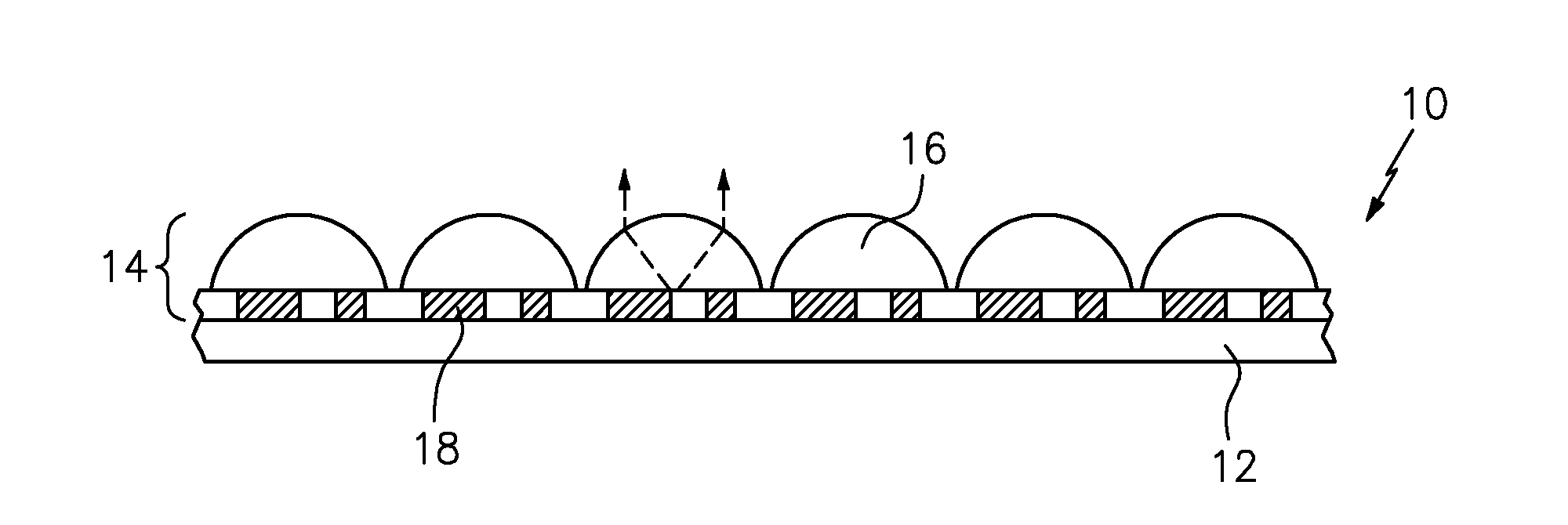
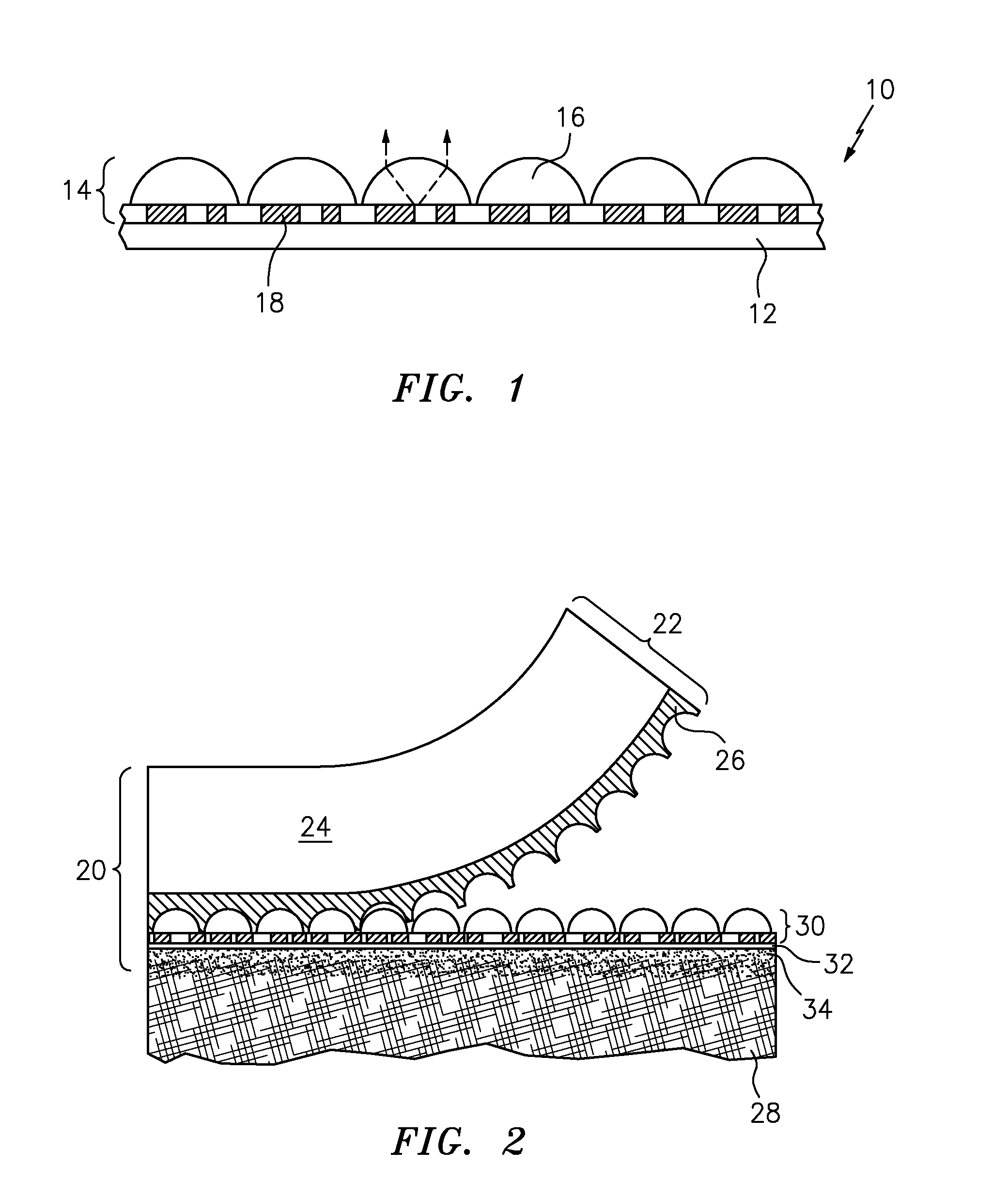
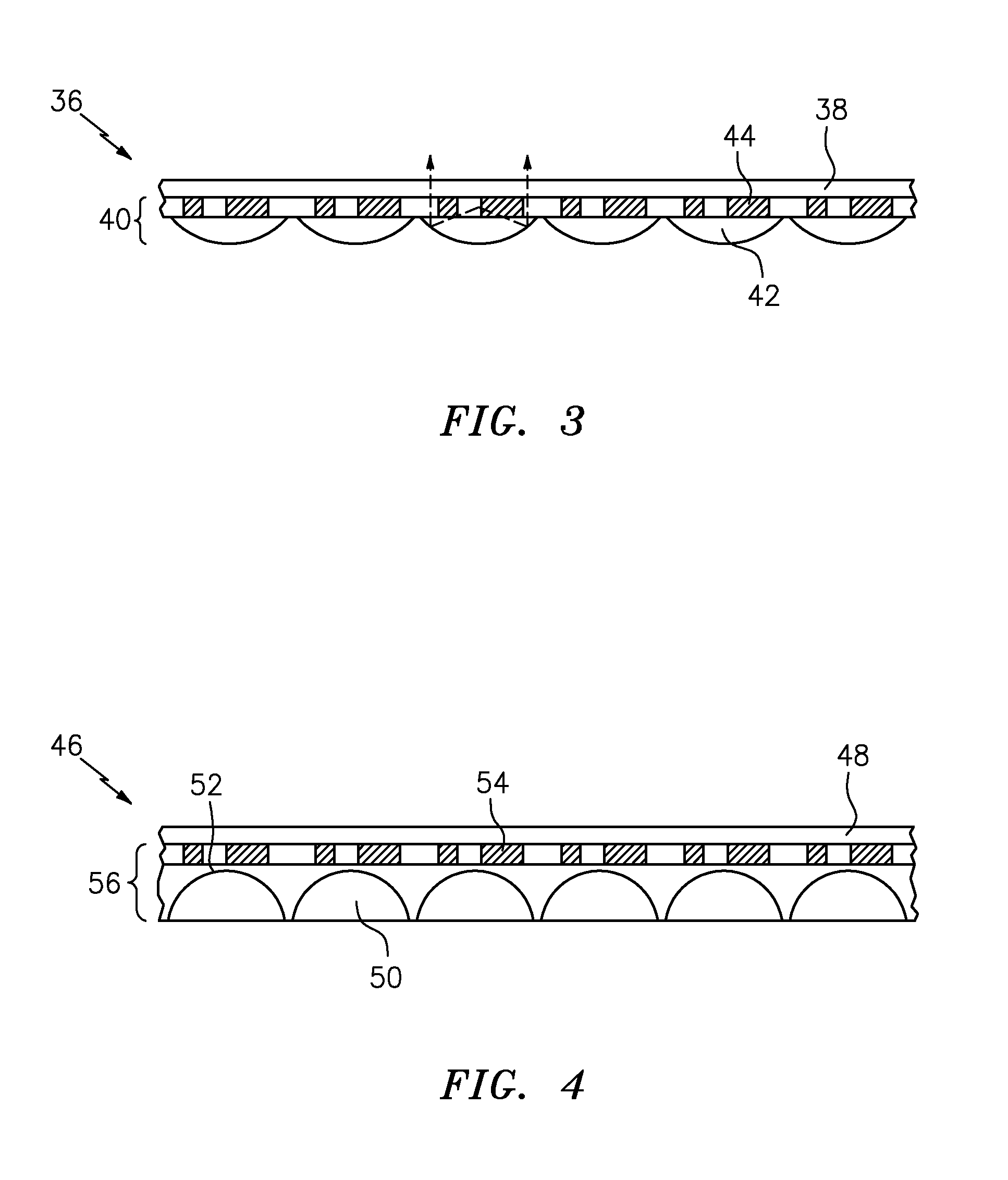
[0023]Exemplary embodiments of the inventive system will now be disclosed in connection with the drawings. There is no intent, however, to limit the present disclosure to the embodiments disclosed herein. On the contrary, the intent is to cover all alternatives, modifications and equivalents. For example, additional features or functionality, such as those described in U.S. Pat. No. 7,333,268 to Steenblik et al., U.S. Pat. No. 7,468,842 to Steenblik et al., and U.S. Pat. No. 7,738,175 to Steenblik et al., may also be included in the invention system. Such additional features or functionality may comprise textured surfaces for better adhesion to further layers, adhesion promoters, etc. The inventive system may also contain overt or covert information such as customized or personalized information in the form of serial numbers, bar codes, images, etc. that can be formed using traditional printing techniques or laser engraving systems. This added functionality would allow interaction b...


PUM


Abstract

An optionally transferable optical system with a reduced thickness is provided. The inventive optical system is basically made up of a synthetic image presentation system in which one or more arrangements of structured image icons are substantially in contact with, but not completely embedded within, one or more arrangements of focusing elements. The focusing element and image icon arrangements cooperate to form at least one synthetic image. By way of the subject invention, the requirement for an optical spacer to provide the necessary focal distance between the focusing elements and their associated image icon(s) is removed. As a result, overall system thicknesses are reduced, suitability as a surface-applied authentication system is enabled, and tamper resistance is improved.

Description

RELATED APPLICATION[0001]This application claims priority to U.S. Provisional Patent Application Ser. No. 61 / 525,239, filed Aug. 19, 2011, which is incorporated herein in its entirety by reference.TECHNICAL FIELD[0002]The present invention generally relates to an improved system for presenting one or more synthetic images, and more particularly relates to an optionally transferable optical system with a reduced thickness.BACKGROUND AND SUMMARY OF THE INVENTION[0003]As described in detail in, for example, U.S. Pat. No. 7,333,268 to Steenblik et al., the focal length of focusing elements in micro-optic materials determines the optical separation of the focusing elements from an image icon array. In other words, the arrays in these micro-optic materials are positioned on either side of an optical spacer so as to align the focal point of each focusing element with its associated image icon(s). When the focal point lies on or within the image icon array, the synthetic image is in sharp f...

Claims


Application Information

Patent Timeline
IPC IPC(8): G02B3/00G02B27/42G02B5/09
CPCG02B3/0006G02B27/4205G02B5/09G02B3/0031B29D11/00278G02B30/27B42D25/324
Inventor JORDAN, GREGORY R.CAPE, SAMUEL M.PALM, SCOTT K.GOSNELL, JONATHAN D.KENNEDY, CAROLINE B.
Owner VISUAL PHYSICS LLC (US)
Why Eureka
Try Eureka