Thermal flask with a vacuum solar heating device

Inactive Publication Date: 2003-09-23
LU CHIH MIN
View PDF6 Cites 9 Cited by
  • Summary
  • Abstract
  • Description
  • Claims
  • Application Information

AI Technical Summary

Problems solved by technology

However, conventional flasks can only keep a liquid hot to the drink but cannot heat the liquid while traveling.
The temperature of the liquid in the

Method used


Image

  • Thermal flask with a vacuum solar heating device
  • Thermal flask with a vacuum solar heating device
  • Thermal flask with a vacuum solar heating device

Examples


first embodiment

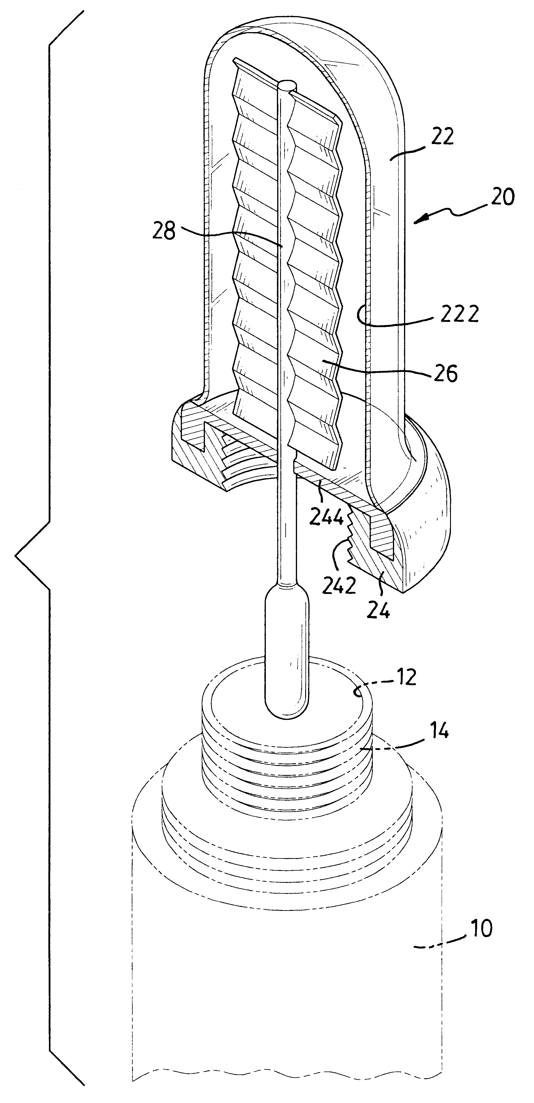
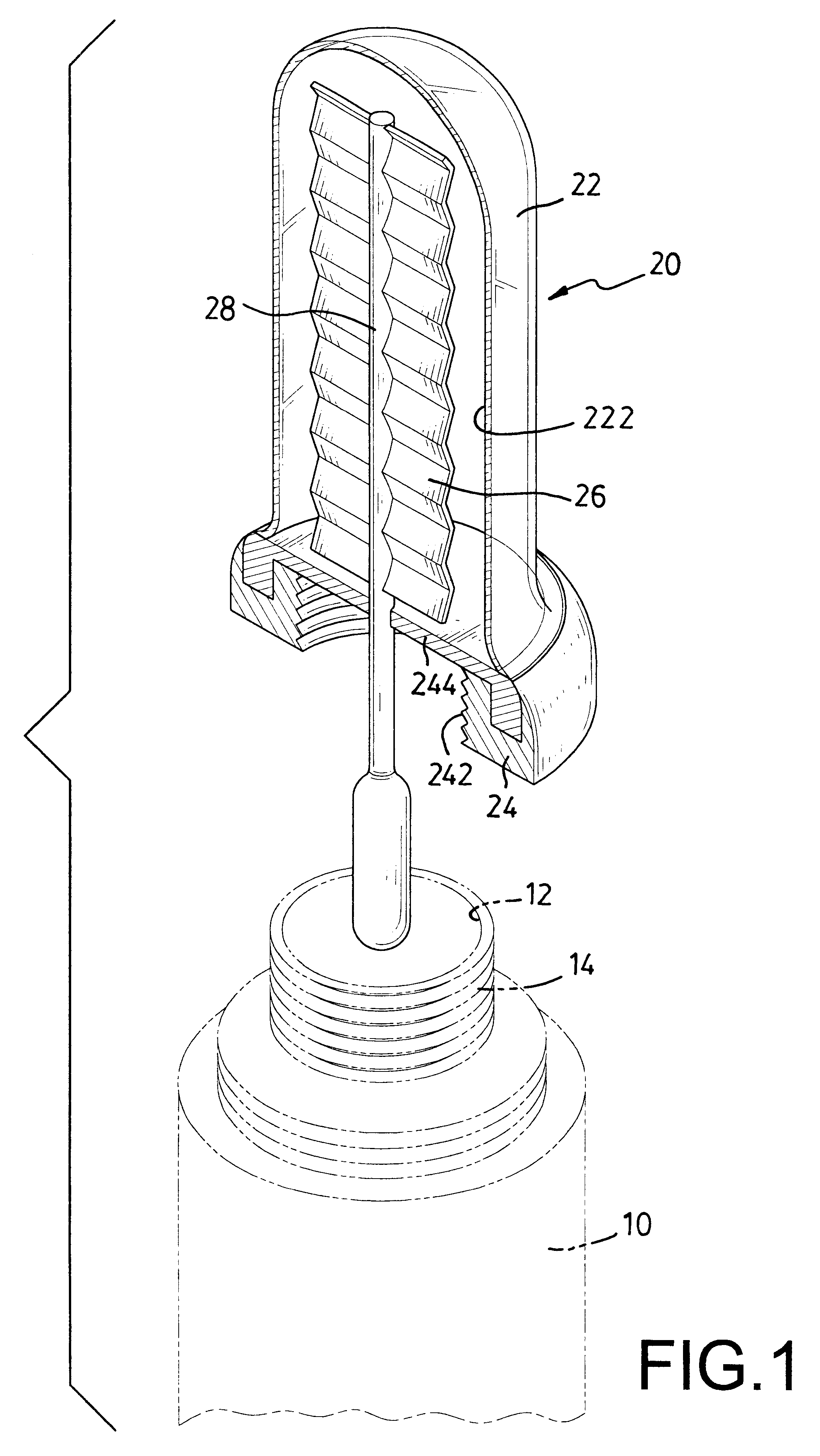
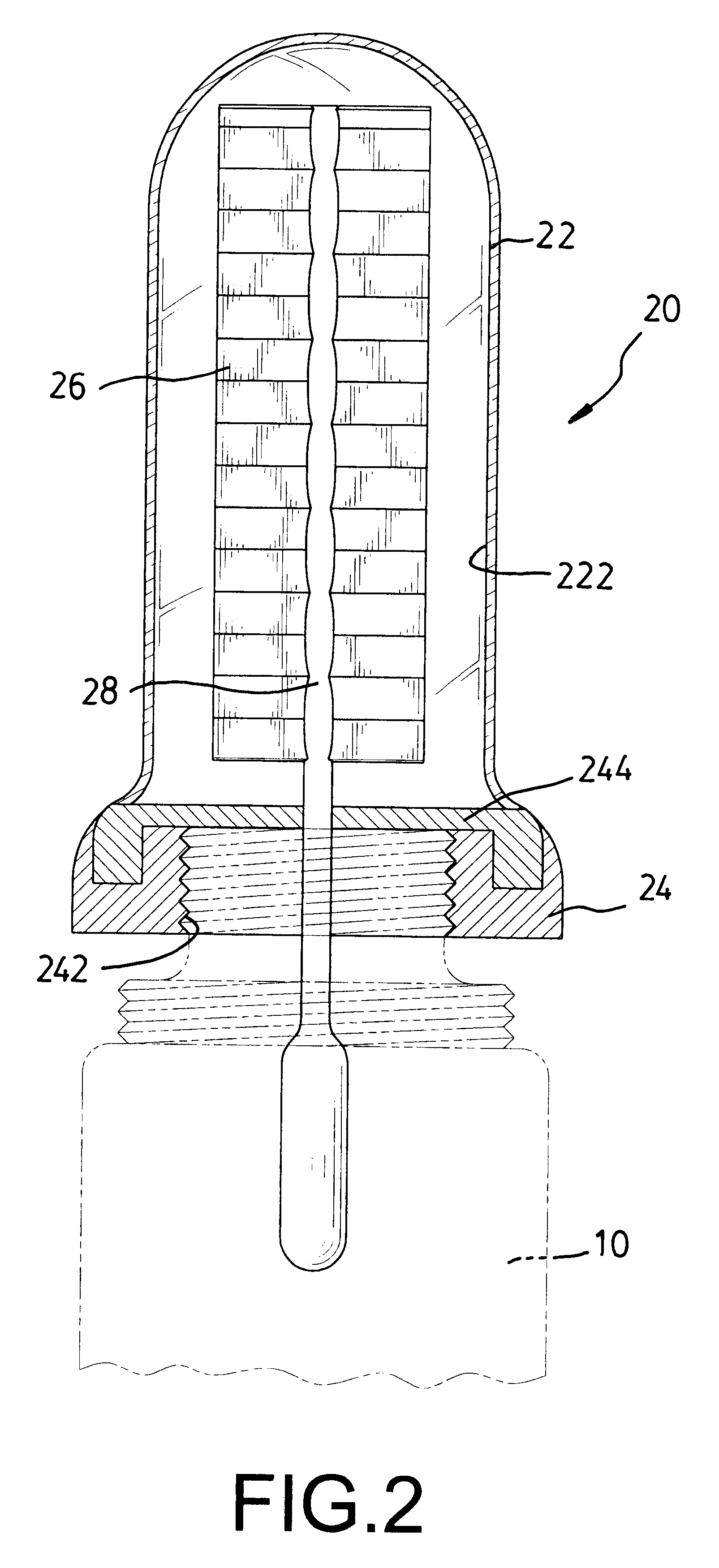
With reference to FIGS. 1 and 2, a thermal flask in accordance with the present invention comprises a hollow body (10) and a vacuum solar heating device (20). The hollow body (10) has an opening (12) defined in the body (10) and an outer thread (14) formed around the opening (12). The vacuum solar heating device (20) is detachably mounted on the opening (12) of the hollow body (10). The vacuum solar heating device (20) comprises a transparent tube (22), a connecting collar (24) and a solar energy absorber. The transparent tube (22) is made of glass and has a closed end and an opened end. The connecting collar (24) is securely attached to the opened end of the tube (22). A vacuum chamber (222) is defined between the tube (22) and the connecting collar (24). An inner thread (242) is formed in the collar (24) to screw onto the outer thread (14) on the hollow body (10). Thus, the tube (22) is detachably mounted on the body (10) by the engagement between the outer thread (14) on the holl...

second embodiment

With reference to FIG. 3, the solar heating device (30) comprises a transparent vacuum tube (32), a connecting collar (34) and a solar energy absorber. The tube has an inner wall, an outer wall and a vacuum chamber (322) formed between the walls. The inner wall has an inner surface. The solar energy absorber is an energy-absorbing coating (36) coated on the inner surface of the inner wall of the tube (32). The solar energy entering into the transparent tube (32) will be absorbed by the coating (36) and will be warmed up the liquid flowing into the tube (32). To heat the liquid in the body (10), the flask is laid down so some of the liquid will flow into the tube (32) through the connecting collar (34). Consequently, the liquid will be heated by the energy absorbed by the energy absorbing coating (36) and converted to heat. Consequently, the liquid will be kept at a desired high temperature for a desired long time.


PUM


Abstract

A thermal flask has a body and a vacuum solar heating device. The solar heating device is detachably mounted on an opening defined in the hollow body. The vacuum solar heating device has a transparent tube, a connecting collar and a solar energy absorber. The tube has an inner wall, an outer wall, a closed end, an open end and a vacuum chamber defined between the inner and outer walls. The connecting collar is mounted on the open end of the tube and has an inner thread screwed onto an outer thread formed around the opening in the hollow body. The solar energy absorber is mounted in the tube to absorb solar energy and radiant heat. Accordingly, the vacuum solar heating device can heat the liquid in the flask, and the temperature of the liquid will be maintained for a desired long time while traveling.

Description

1. Field of the InventionThe present invention relates to a container, and more particularly to a thermal flask with a vacuum solar heating device that can heat liquid in the flask by solar energy.2. Description of Related ArtA thermal flask is a container that can be used to carry liquid. Flasks are vacuum-insulated to keep the liquid hot or cold for a long period of time. However, conventional flasks can only keep a liquid hot to the drink but cannot heat the liquid while traveling. The temperature of the liquid in the flask will gradually approach ambient temperature, and the heat preserving effect of the flask cannot be maintained for a desired extremely long time.To overcome the shortcoming, the present invention provides a thermal flask with a vacuum solar heating device to mitigate or obviate the aforementioned problem, and utilizes the free and clean solar power.The main objective of the invention is to provide a thermal flask with a vacuum solar heating device to heat the l...

Claims


Application Information

Patent Timeline
IPC IPC(8): A47J41/00
CPCA47J41/005F24S10/45F24S10/75F24S10/90Y02E10/44
Inventor LU, CHIH-MIN
Owner LU CHIH MIN
Why Eureka
Try Eureka