Touch panel input device capable of sensing input operation using a pen and a fingertip and method therefore

a technology of input device and touch panel, which is applied in the direction of instruments, cathode-ray tube indicators, computing, etc., can solve the problems of affecting the operation of the input device, unable to easily bring the upper transparent resistive, and relatively weak load

Inactive Publication Date: 2003-09-30
NEC CORP
View PDF10 Cites 147 Cited by
  • Summary
  • Abstract
  • Description
  • Claims
  • Application Information

AI Technical Summary

Problems solved by technology

In operation, even when other than a pen, for example, a part of the user such as a palm touches the touch panel, an erroneous operation does not easily take place.
Therefore, the load is relatively weaker and does not easily bring the upper transparent resistive film into contact with the lower transparent resistive film.
Therefore, in a pen-input mode, when a part of a hand mistakenly touches the touch panel, an erroneous input easily takes place.

Method used


Image

  • Touch panel input device capable of sensing input operation using a pen and a fingertip and method therefore
  • Touch panel input device capable of sensing input operation using a pen and a fingertip and method therefore
  • Touch panel input device capable of sensing input operation using a pen and a fingertip and method therefore

Examples


first embodiment

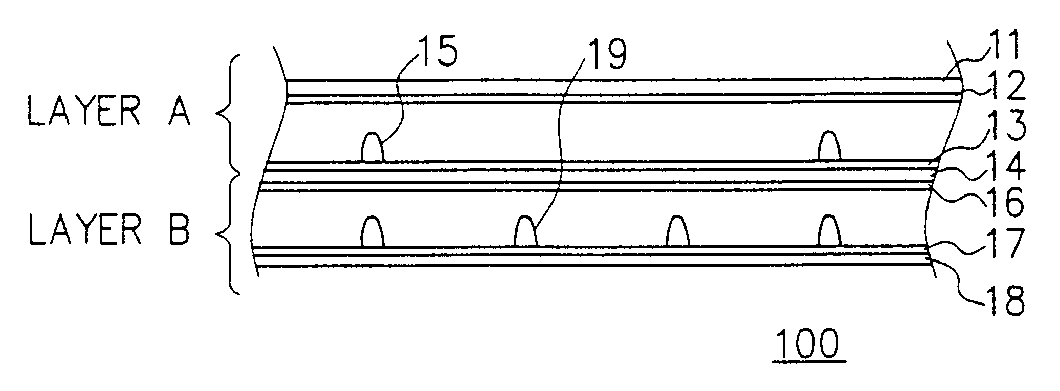
FIG. 7 shows in a cross-sectional view and outline of constitution of a first embodiment of a touch panel input device in accordance with the present invention. Shown in FIG. 7, a first embodiment of a touch panel input device 100 primarily includes two layers, namely, a first touch panel is layer A and a second touch panel is layer B.

Layer A disposed on an upper side in FIG. 7 includes, in a downward direction, a first transparent film 11, a first transparent resistive film 12, a second transparent resistive film 13, a second transparent film 14, and first dot spacers 15.

Layer B arranged on a lower side in FIG. 7 includes, in a downward direction, a third transparent resistive film 16, a fourth transparent resistive film 17, a glass substrate 18, and second dot spacers 19.

Preferably, as shown in FIG. 7, the first dot spacers 15 are higher density than the second dot spacers 19, for example, 2 times or more. However, the present invention contains the state of the density of the spa...

second embodiment

The second embodiment is a handwritten image input device using a touch panel. The touch panel input device of the present invention can determine a finger input operation and a pen input operation as described in conjunction with the first embodiment.

When it is determined that a pen input operation is conducted, the touch panel input device of the second embodiment receives, like the first embodiment, coordinates of a contact point of layer B of the touch panel shown in FIG. 7. In the second embodiment of the touch panel input device, points corresponding to the coordinates received from the touch panel 21 are drawn on the display section 24. Therefore, by drawing a picture on the touch panel 21 by a pen as shown in FIG. 17, an image of the handwritten picture can be displayed on the display section 24.

When the touch panel input device of the second embodiment determines that data is input by a fingertip, coordinates are received from layer A of the touch panel shown in FIG. 7 as i...

third embodiment

The third embodiment differs from the first and second embodiments in that the second transparent film 14 shown in FIG. 7 is substituted for two independent transparent films 14a and 14b.

Therefore, layers A and B are electrically and / or structurally independent completely touch panels. By simply attaching two touch panels to each other, there can be implemented a device similar to the touch panels of the first and second embodiments.

For the touch panel of layer B of FIG. 19, a general touch panel of the prior art is available. In the touch panel of layer A in FIG. 19, only the material of the bottom section is changed from glass to a film. Consequently, a touch panel production process of the prior art can be directly used and hence the initial cost can be minimized and productivity can be increased.

The embodiments described above are preferred embodiments of the present invention and can be changed and modified within a scope of the present invention.

As can be understood from the d...


PUM


Abstract

A touch panel input device includes layers A and B. Layer A includes a first transparent film, a first transparent resistive film, a second transparent film, a second transparent resistive film, and first dot spacers. Layer B includes a second transparent film, a third transparent resistive film, a fourth transparent resistive film, a glass substrate, and second dot spacers. When the device is operated by a finger, the device detects a contact state of the transparent resistive films in layer A and a non-contact state of the transparent resistive films in layer B. When the device is operated by a finger, the device detects a contact state of the transparent resistive films in layer A and a contact state of the transparent resistive films in layer B. Regardless of the input mode, information of a position thus inputted can be detected. The touch panel input device detects, regardless of the input mode to use a pen or a finger, information of a position inputted by a pen or by a finger.

Description

The present invention relates to a touch panel input device, and in particular, to a touch panel input device which is disposed in a display section including a liquid-crystal device (LCD) and in which a coordinate signal is sensed using a change in a position depressed by a finger (fingertip), a pen or the same in association with a content displayed on the display section and the coordinate signal thus sensed is inputted to a device connected to the touch panel input device.DESCRIPTION OF THE PRIOR ARTA touch panel input devices of prior art include a touch panel of transparent resistive film type. FIG. 1 shows in a cross-sectional view a configuration of the touch panel using transparent resistive films 500 of the prior art.The touch panel 500 shown in FIG. 1 includes a transparent film 51, a first transparent resist film 52, a second transparent resistive film 53, a glass substrate 54, and a dot spacers 55 disposed over an upper surface of the second transparent resistive film 5...

Claims


Application Information

Patent Timeline
Patent Type & Authority Patents(United States)
IPC IPC(8): G06F3/033G06F3/041G06F3/045H01H13/712
CPCG06F3/045G06F3/04883
Inventor SHIMIZU, TOSHIYUKI
Owner NEC CORP
Why Eureka
Try Eureka