Plastic wheel assembly and mounting sleeve with stabilizing recess
What is AI technical title?
AI technical title is built by PatSnap AI team. It summarizes the technical point description of the patent document.
a technology of stabilizing recess and wheel assembly, which is applied in the direction of refusing gathering, transportation and packaging, hubs, etc., can solve the problems of difficult removal of such plastic wheels in order to replace or repair the wheel or the cart, damage to the axle, and the area of the sleeve which includes the displaceable finger is less stable, less capable of supporting shifting or rocking along the axle,
Inactive Publication Date: 2003-10-28
GEO PLASTICS
View PDF14 Cites 62 Cited by
Summary
Abstract
Description
Claims
Application Information
AI Technical Summary
This helps you quickly interpret patents by identifying the three key elements:
Problems solved by technology
Method used
Benefits of technology
Benefits of technology
The solution provides a durable, stable, and cost-effective wheel assembly capable of withstanding shock loads and vibrations, with reduced material usage while maintaining stability and ease of assembly / disassembly, suitable for small diameter axles and smaller wheeled products.
Problems solved by technology
Removal of such plastic wheels in order to replace or repair the wheel or the cart has been difficult because the hammered hubs require special tools for their removal or essentially must be destroyed to remove them from the axle.
Sometimes this process also damages the axles.
Since such mounting sleeves often employ resiliently transversely displaceable fingers to lock or latch the wheel to the axle, the area of the sleeve which includes the displaceable finger tends to be somewhat less stable and less capable of supporting shifting or rocking along ther axle and transverse loads on the axle.
Prior art snap-on wheel-mounting assemblies have been unduly complex, visually unappealing, and not well suited to the shock loading and vibration which is commonly encountered.
They also are not easily adaptable for use on smaller axles and smaller wheeled products.
Moreover, the cost of prior art snap-on couplings has been undesirably high, as has their rate of failure.
This approach is based, in part, upon mating frictional engagement of the hub halves, but under the shock loading and high vibration which refuse carts, cooler and toys typically experience, frictional securement of components can be unreliable.
The need for multiple hub pieces and an axle with an enlarged head, also is not desirable and the end of the axle is not supported well against transverse loading.
Such notched or grooved axles are in wide spread use in connection with trash carts, but this assembly again requires multiple pieces and, in this case, special tools and tedious manipulation are required in order to release the resilient retainer ring fingers from the inside of the wheel so that the wheel can be removed from the axle.
As will be seen, however, both of the wheel-mounting sleeve assemblies in these patents are relatively complex and employ a plurality of pieces in order to secure the wheel on the axle.
As the wheel and axle size reduces, therefore, these assemblies become more difficult to employ.
In U.S. Pat. Nos. 5,277,480 and 5,902,018 separate retainer devices are used with sleeves, but the outer ends of the axles are essentially unsupported and hub covers must be employed for safety and / or aesthetic reasons.
Method used
Image
Click on the blue label to locate the original text in one second.
Reading with bidirectional positioning of images and text.
Examples
Embodiment Construction
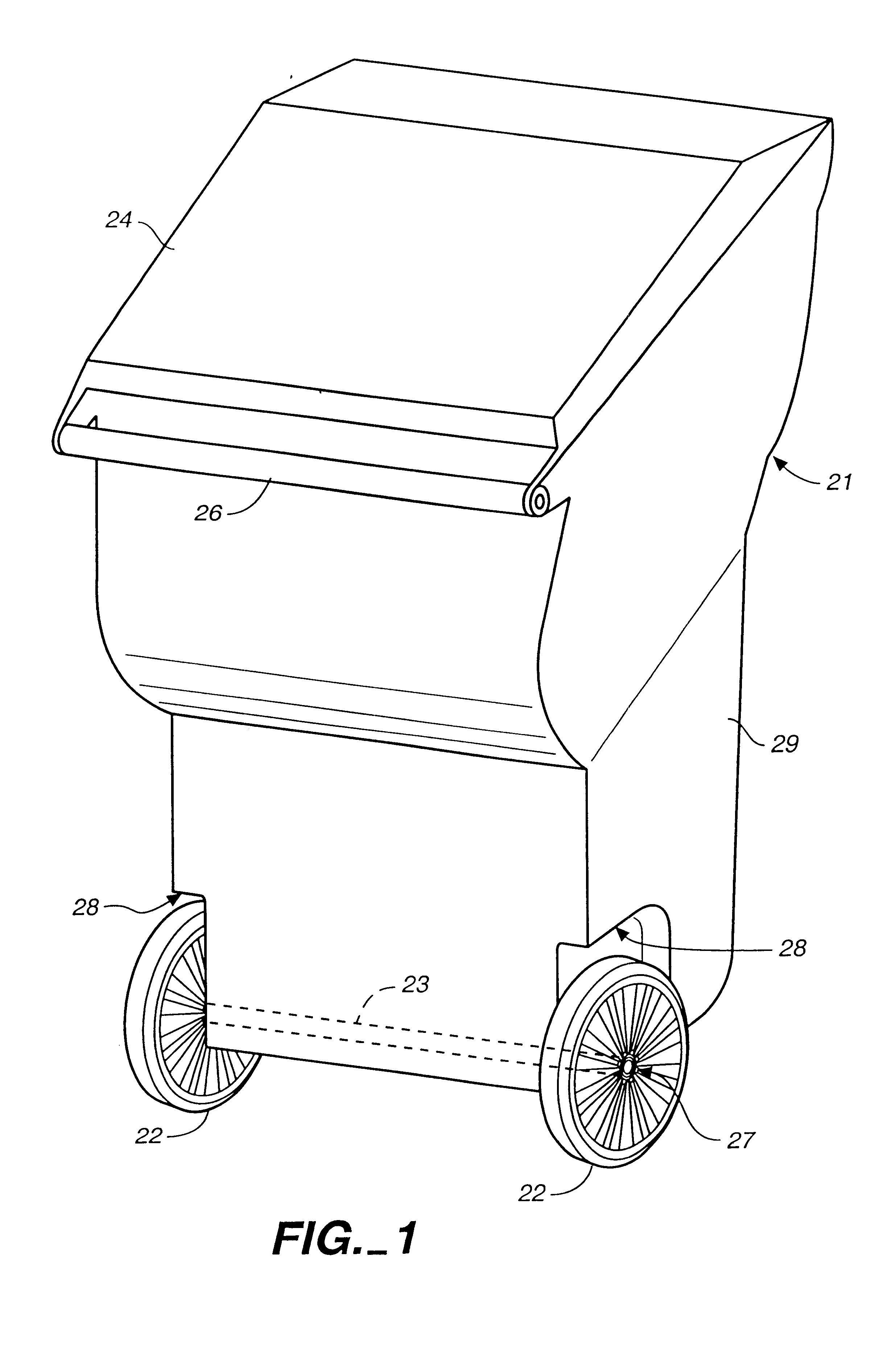
The wheel mounting sleeve and wheel assembly of the present invention can be used in connection with numerous wheeled devices. A typical, but not limiting, application is to employ the same in a wheeled refuse cart or container of the general type shown in FIG. 1. Thus, cart 21 includes a pair of wheels 22 mounted on an axle 23 to the lower end of the cart body 29. A hinged lid 24 optionally can be provided, and the cart can be tilted or tipped about the wheels using handle 26 so as to enable rolling of the cart for the transport of refuse, for example, between a location for filling the cart and a location for pickup by a refuse disposal company.
Wheels 22 are secured on axle 23 by a wheel mounting sleeve, generally designated 27. In the refuse cart illustrated, body 29 of the cart includes a wheel well or recess area 28 which receives wheels 22, in part to protect the wheels and in part as a cosmetic structure. Many carts, however, do not include wheel wells as illustrated.
Similar ...
PUM
Abstract
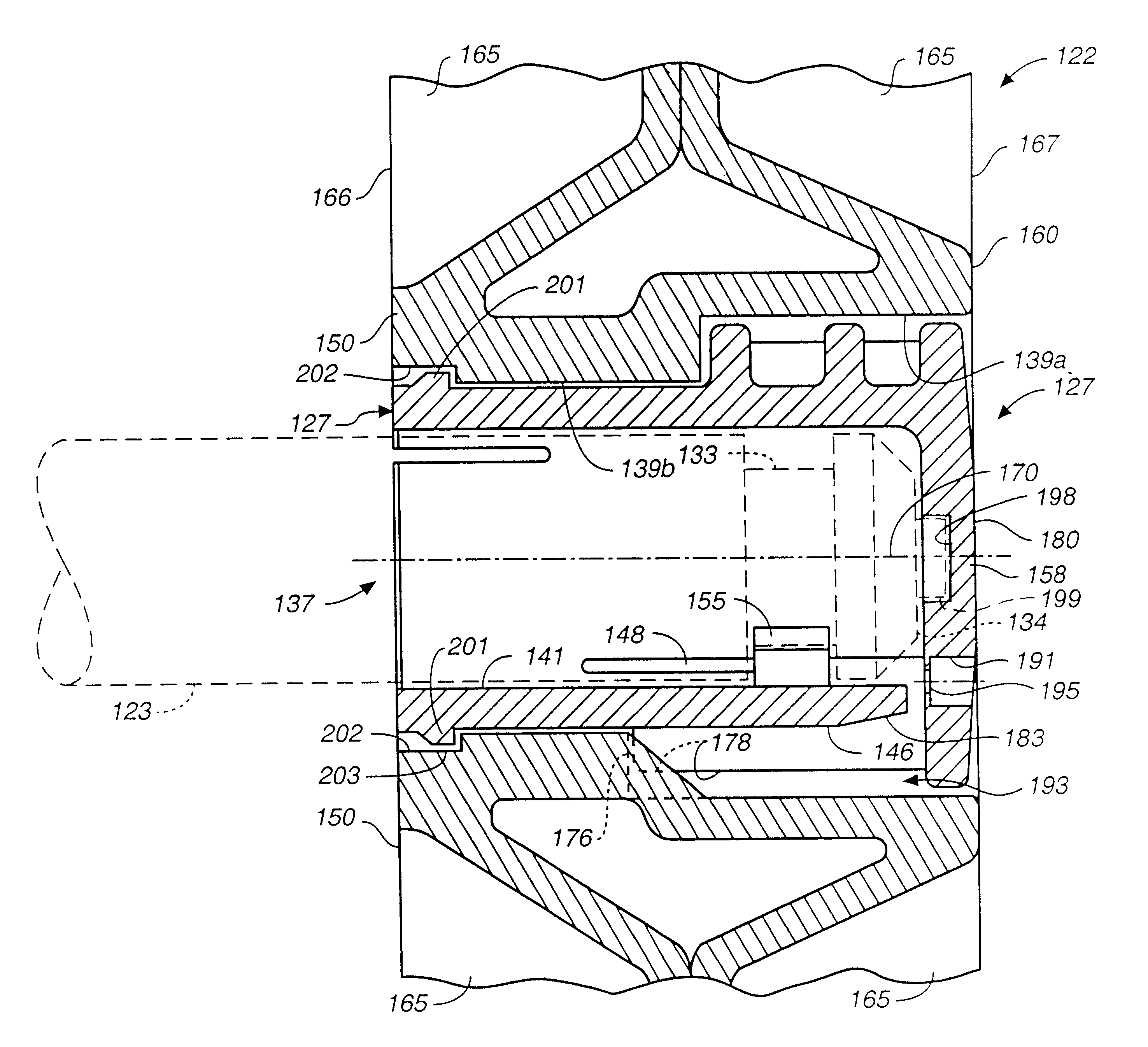
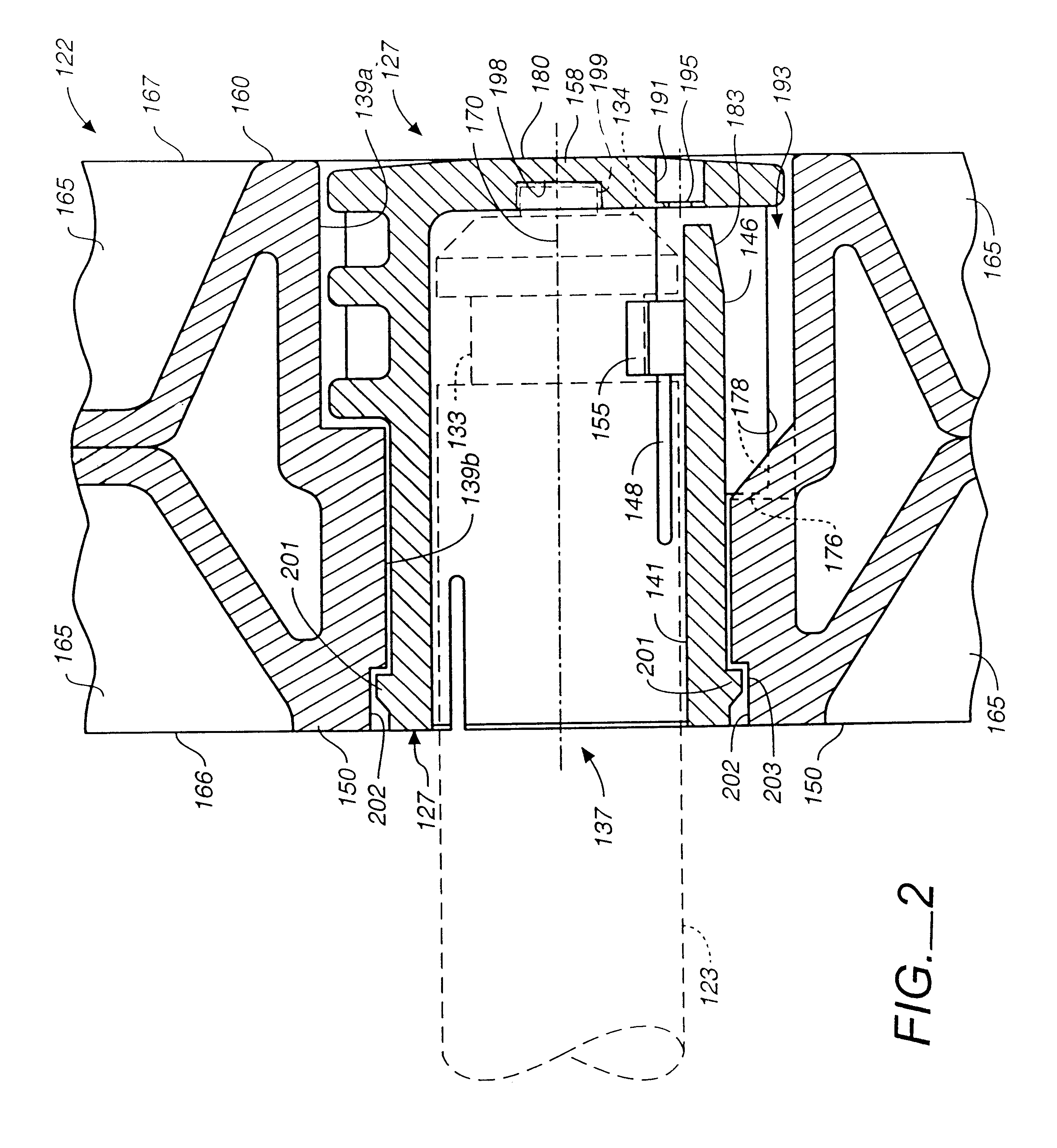
A plastic wheel (122, 222) and wheel mounting sleeve (127, 227, 327, 427) used to releasably secure the wheel (122, 222) onto an axle (123, 223). The wheel mounting sleeve (127, 227, 327, 427) preferably includes a resilient, radially displaceable, axially extending, cantilevered finger (146, 246, 346, 446) which includes an axle-engaging lug (155, 255, 355, 455), while a wheel-engaging shoulder is provided on the sleeve by an annular rib (201, 301). The sleeve shoulders latch the sleeve (127, 227, 327, 427) to the axle (123, 223) and the wheel (122, 222) to the sleeve. The sleeve (127, 227, 327, 427) includes an axle stabilizing recess (198, 298, 398, 498) positioned in an end wall (158, 258, 358, 458), which receives an axle stub (199, 299) that supports the axle (123, 223) against lateral loading and stabilizes it to reduce wobble, chatter and vibration.
Description
The present invention relates, in general, to wheel assemblies and the manner of their mounting to and removal from an axle, and more particularly, relates to plastic wheel assemblies of the type used on refuse carts, wheeled coolers, wagons, wheeled toys, barbecues or the like.The use of plastic wheels on a variety of products has dramatically increased in recent years. One area where such plastic wheels have been widely employed is on wheeled refuse or garbage carts or bins of the type commonly employed by homeowners for their trash. Typically, these carts are formed of an injection, blow or rotationally molded plastic and have injection or blow molded plastic wheels which are mounted on the ends of a metal axle by a hub member. The wheel hub is hammered onto the end of the axle to hold the wheel in place. Removal of such plastic wheels in order to replace or repair the wheel or the cart has been difficult because the hammered hubs require special tools for their removal or essent...
Claims
Application Information
Patent Timeline
Application Date:The date an application was filed.
Publication Date:The date a patent or application was officially published.
First Publication Date:The earliest publication date of a patent with the same application number.
Issue Date:Publication date of the patent grant document.
PCT Entry Date:The Entry date of PCT National Phase.
Estimated Expiry Date:The statutory expiry date of a patent right according to the Patent Law, and it is the longest term of protection that the patent right can achieve without the termination of the patent right due to other reasons(Term extension factor has been taken into account ).
Invalid Date:Actual expiry date is based on effective date or publication date of legal transaction data of invalid patent.

