Method of automatic continuous calibration for an electronic compass

an electronic compass and continuous calibration technology, applied in the field of electronic compasses, can solve the problems of insufficient accuracy, affecting the readings and headings of electronic compasses, and objects affecting the readings of compasses, so as to improve accuracy, reduce the effect of manual calibration, and accurately compensate for local changes

Inactive Publication Date: 2003-11-18
INNOVATIVE DESIGN SOLUTIONS
View PDF14 Cites 75 Cited by
  • Summary
  • Abstract
  • Description
  • Claims
  • Application Information

AI Technical Summary

Benefits of technology

One advantage of the present invention is that the method of continuous calibration will more accurately compensate for local changes in the magnetic disturbances associated with electronic compasses.
is that the method of continuous calibration will more accurately compensate for local changes in the magnetic disturbances associated with electronic compasses.
A further advantage of the present invention is that the calibration routine or method uses two separate sets of minimum and maximum values to determine if the compass has gone in a full circle and in determining the heading of the compass.
A further advantage of the present invention is that the method does not use an extended history of sensor data to determine the compasses current movement. Therefore, the compass is able to recalibrate itself more quickly, efficiently and rapidly, when operating in a dynamic magnetic environment that changes due to variations in stray / ambient magnetic fields and changes in the ferrous material near the compass, such as found in a vehicle.
A further advantage of the present invention is that the calibration method is capable of varying the rate at which the calibration is updated in order to respond more quickly and accurately to changes in the local magnetic environment.
A further advantage of the present invention is that by the adjustment of certain parameters the algorithm is highly adaptive to allow for accurate heading determination in various operating environments.

Problems solved by technology

However, they have an inherent problem that magnetic disturbances in the environment will affect the electronic compass readings and headings.
Furthermore, any nearby electronic devices and ferrous objects will also affect the compass readings.
Prior art devices have tried to compensate for the deviation of ferrous objects and magnetic distortions and / or disturbance but the accuracy is still not sufficient.

Method used


Image

  • Method of automatic continuous calibration for an electronic compass
  • Method of automatic continuous calibration for an electronic compass
  • Method of automatic continuous calibration for an electronic compass

Examples


Embodiment Construction

)

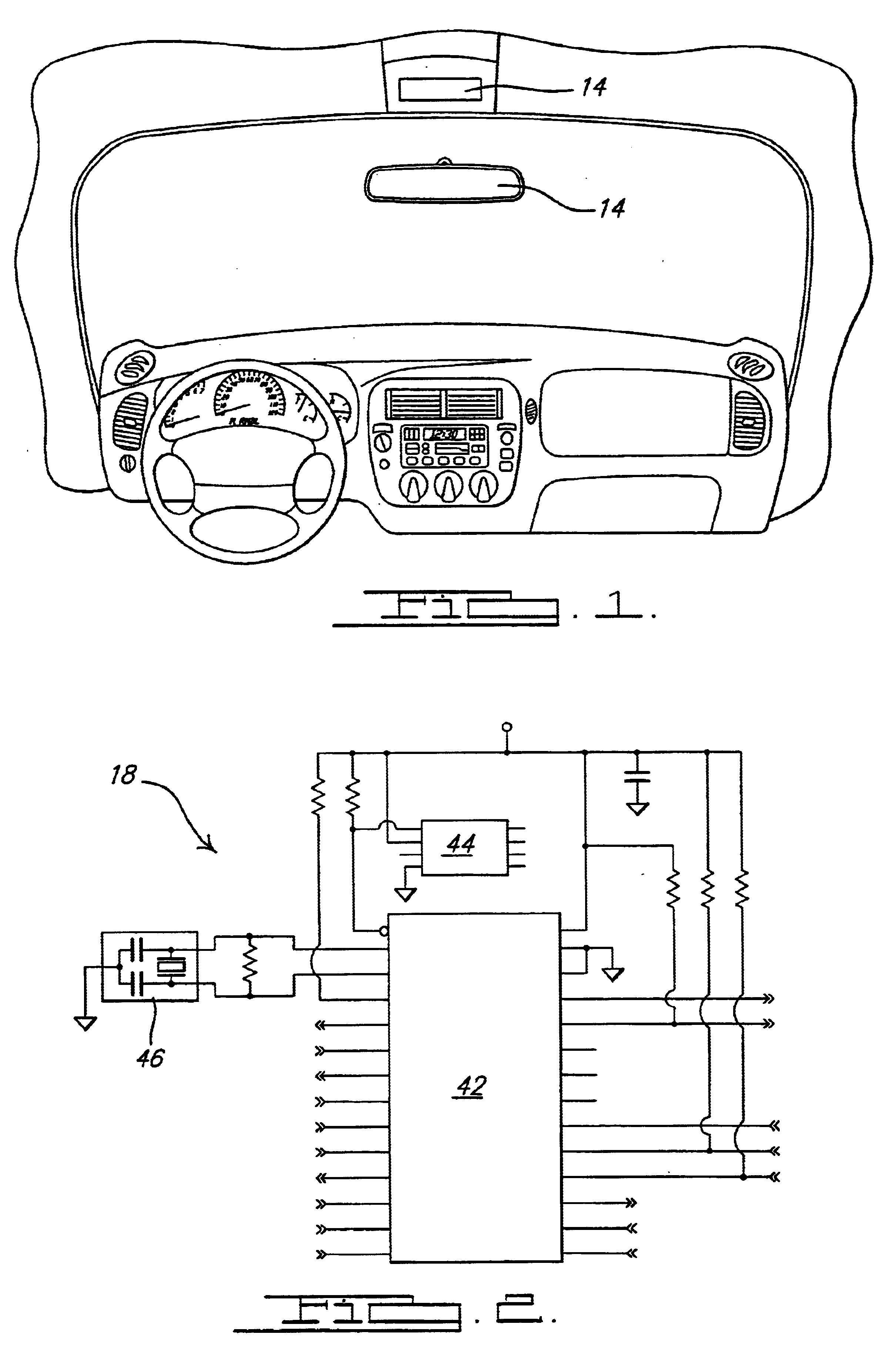
Referring to the drawings, a method of continuous calibration for an electronic compass according to the present invention is shown. The continuous calibration method is used generally for electronic compasses in vehicles. However, it should be noted that the compasses can be used in hand-held situations, in air crafts, and marine craft depending on the need and the environment for the compass. A common automotive interior configuration is shown in FIG. 1, the electronic compass 14 is either placed within an overhead console or within the rear view mirror surface itself. The compass may be a single piece unit that contains all of the compass hardware and software in one unit. A second embodiment is a dual piece unit that would separate the magnetic sensor from the display device. The magnetic sensor and the associated signal conditioning circuitry would be located on one unit while the display device would be located on a second unit remote from the first unit. The dual unit config...


PUM


Abstract

An autocalibration method for use within an electronic compass in a vehicle is disclosed. The method includes steps of initializing variables and then retrieving sensor readings from at least two axis. The method then compares the compass tilt to a predetermined threshold. Next the method will determine if the sensor reading is a minimum or maximum for the current calibration cycle. Next the method will determine if the maximum value of the sensor readings is greater than the predetermined minimum spread. Then the method will calculate an offset value for each axis and calculate a sensor value for each axis. Then the method will calculate an azimuth value with the new sensor values and determine the heading using the azimuth.

Description

1. Field of the InventionThe present invention relates generally to electronic compasses for use in vehicles, and more particularly, relates to a method of automatic continuous calibration of an electronic compass for use in a vehicle.2. Description of Related ArtMagnetic compasses are commonly used in vehicles, including land vehicles, boats, air craft and even by hikers, as an aide in direction finding and navigation. The popularity has increased for use of the electronic compasses in motor vehicles, in either the rearview mirror or on a separate overhead console unit. Meanwhile, the manufacturers of the vehicles are increasingly asking for more accurate and low cost compass products for their vehicles.Generally speaking, vehicles use one of two compass products. The first is a two board system where a remote sensor board communicates through a display via a wiring harness. The second type is a single board system consisting of a sensor board which transmits the heading informatio...

Claims


Application Information

Patent Timeline
Patent Type & Authority Patents(United States)
IPC IPC(8): G01C17/00G01C17/38
CPCG01C17/38
Inventor WOLOSZYK, MARKMANFREDA, JOHNFORD, ROBERTHALEY, SHAWN
Owner INNOVATIVE DESIGN SOLUTIONS
Why Eureka
Try Eureka