Protective skin for optical fibers

a technology for protecting skin and optical fibers, applied in the direction of optical elements, cables, instruments, etc., can solve the problems of not being very flexible, reducing protection, and not enabling the fiber to be accessed with the fingers

Inactive Publication Date: 2003-12-02
ALCATEL LUCENT SAS
View PDF16 Cites 189 Cited by
  • Summary
  • Abstract
  • Description
  • Claims
  • Application Information

AI Technical Summary

Problems solved by technology

Nevertheless, those tubes suffer in particular from the drawback of not enabling the fibers to be accessed with the fingers unless special tools are used, and of not being very flexible.
Unfortunately, at a temperature above the melting point of the polymers used, the modules run the risk of sticking together, and that can reduce protection, while also making it more difficult or even impossible to access the fibers and to identify them.

Method used


Image

  • Protective skin for optical fibers
  • Protective skin for optical fibers

Examples


Embodiment Construction

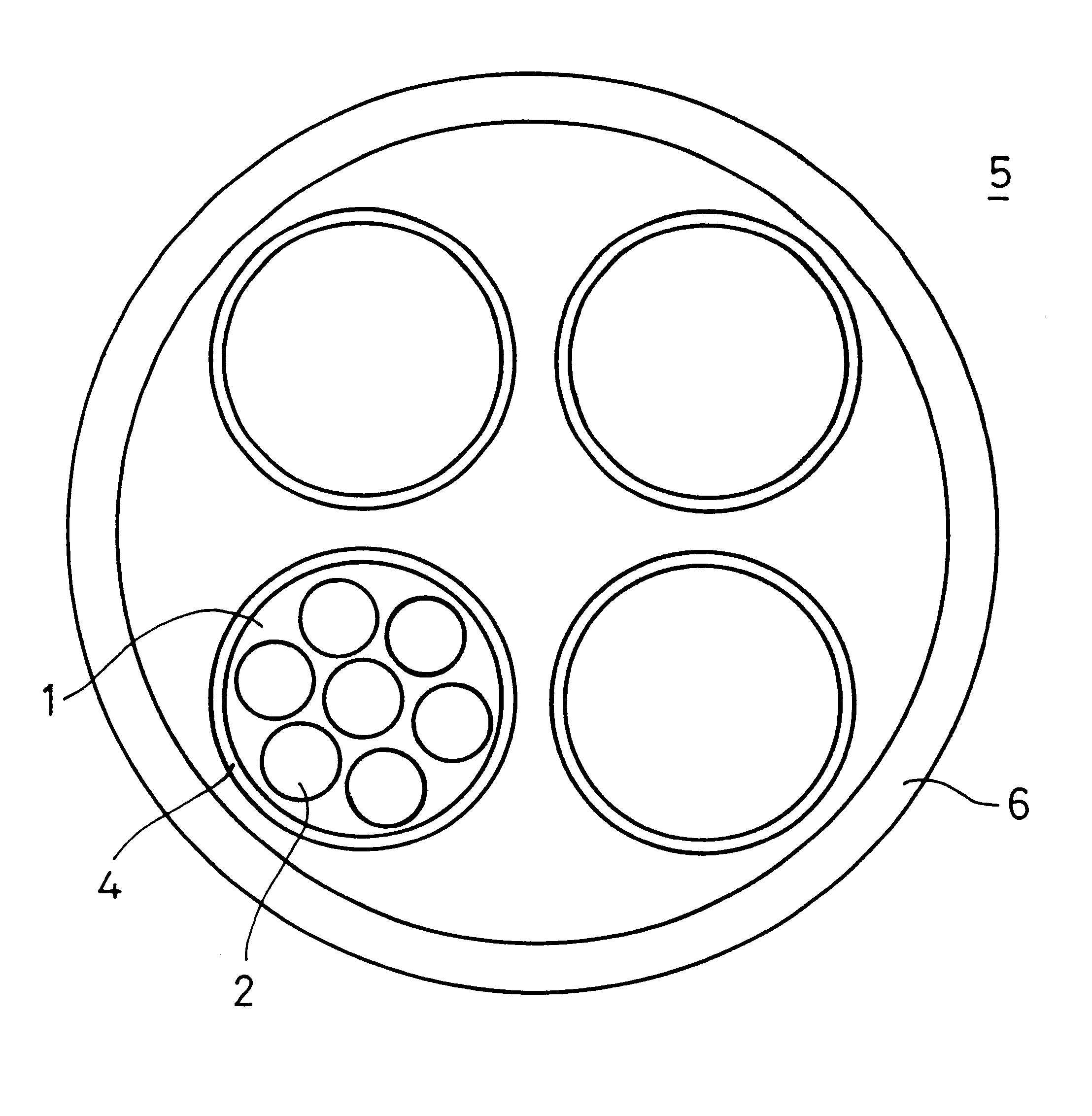
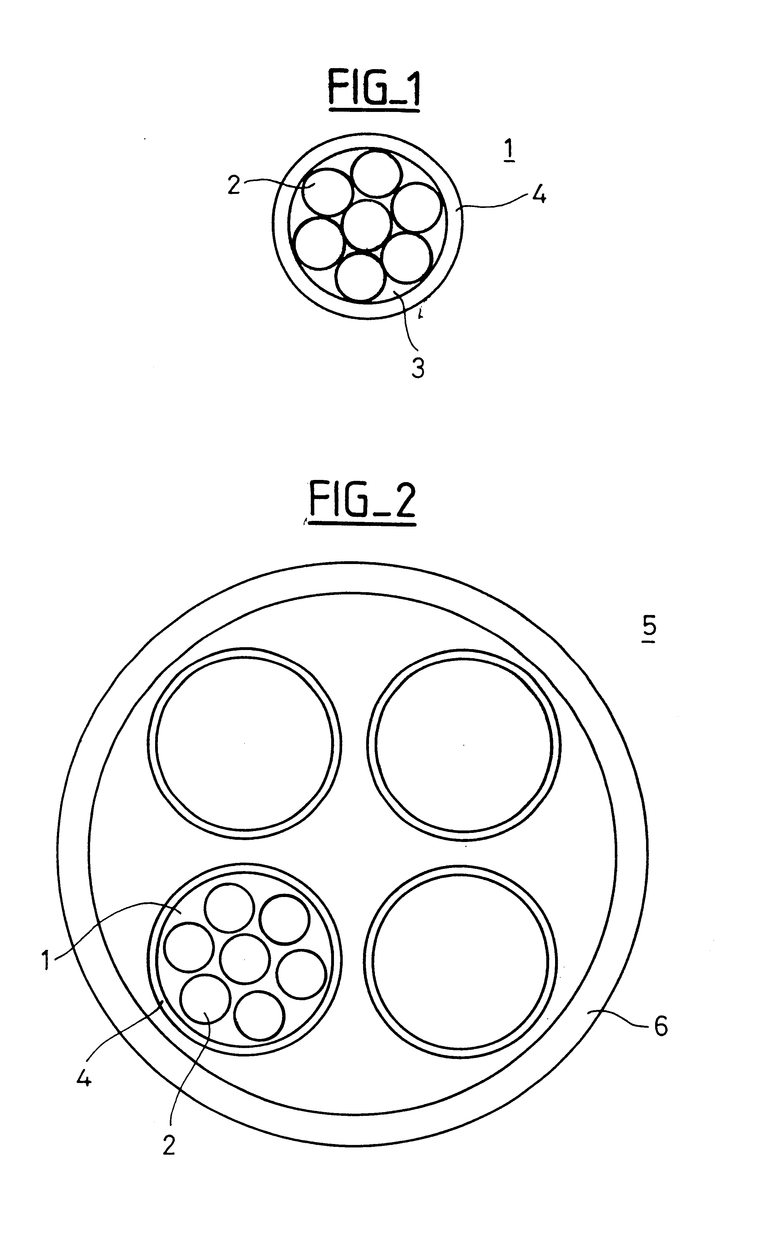
FIG. 1 is a section view of a telecommunications cable module 1 comprising at least one and generally a plurality of optical fibers 2. The optical fibers 2 are surrounded by a flexible tube 4 referred to as a "skin". The gaps between the fibers are general occupied by a hydrophobic gel 3, e.g. based on silicones.

It is also possible to use a powder that swells, or to leave nothing between the fibers. The skin 4 is applied to the set of optical fibers, e.g. by extrusion. The thickness of the skin 4 is preferably small, e.g. lying in the range 0.05 millimeters (mm) to 0.25 mm, and is preferably 0.15 mm. Small thickness is desirable insofar as it facilities access to the fiber and makes it possible to reduce the overall weight of the cable. The lower limit of thickness is given by the protection which the skin gives to the fiber, and by the constraints involved in manufacturing the skin.

FIG. 2 is a diagram of a telecommunications cable 5 having a plurality of optical fiber modules 1. Th...


PUM

PropertyMeasurementUnit
melting pointaaaaaaaaaa
breaking elongationaaaaaaaaaa

Abstract

The invention relates to a telecommunications cable module comprising at least one optical fiber surrounded by a protective skin of a thermoplastic elastomer having flexible diol segments, and in particular a polyester thermoplastic elastomer. In the invention, the thermoplastic elastomer having flexible diol segments presents a melting point greater than 130° C. and an initial resistance to tearing less than 60 kN / m. The material proposed by the invention is easily applied to fibers, in particular by extrusion.

Description

The present invention relates to telecommunications cables. It relates more particularly to cables containing optical fibers disposed in a tube made of a thermoplastic elastomer having flexible diol segments, and in particular a thermoplastic polyester elastomer.An optical fiber cable is generally constituted by an outer sheath and metal or dielectric protective reinforcing elements together surrounding a plurality of modules, each comprising a plurality of fibers surrounded by a protective tube. The purpose of these tubes is to protect the fibers both mechanically and chemically, and they are also used for identifying the modules. For example, a 144-fiber cable comprises 12 tubes each containing 12 fibers, the tubes being assembled around a central carrier, and the entire assembly being surrounded by a sheath of polyethylene. The fibers are individually colored within each tube, and the tubes are themselves colored.It is known to place optical fibers in tubes that are rigid and thi...

Claims


Application Information

Patent Timeline
Patent Type & Authority Patents(United States)
IPC IPC(8): G02B6/44H01B11/00H01B13/00
CPCG02B6/443G02B6/441
Inventor BOURGET, VINCENTDRABCZYK, NELLY
Owner ALCATEL LUCENT SAS
Why Eureka
Try Eureka