Crimping terminal for connection between electric cables

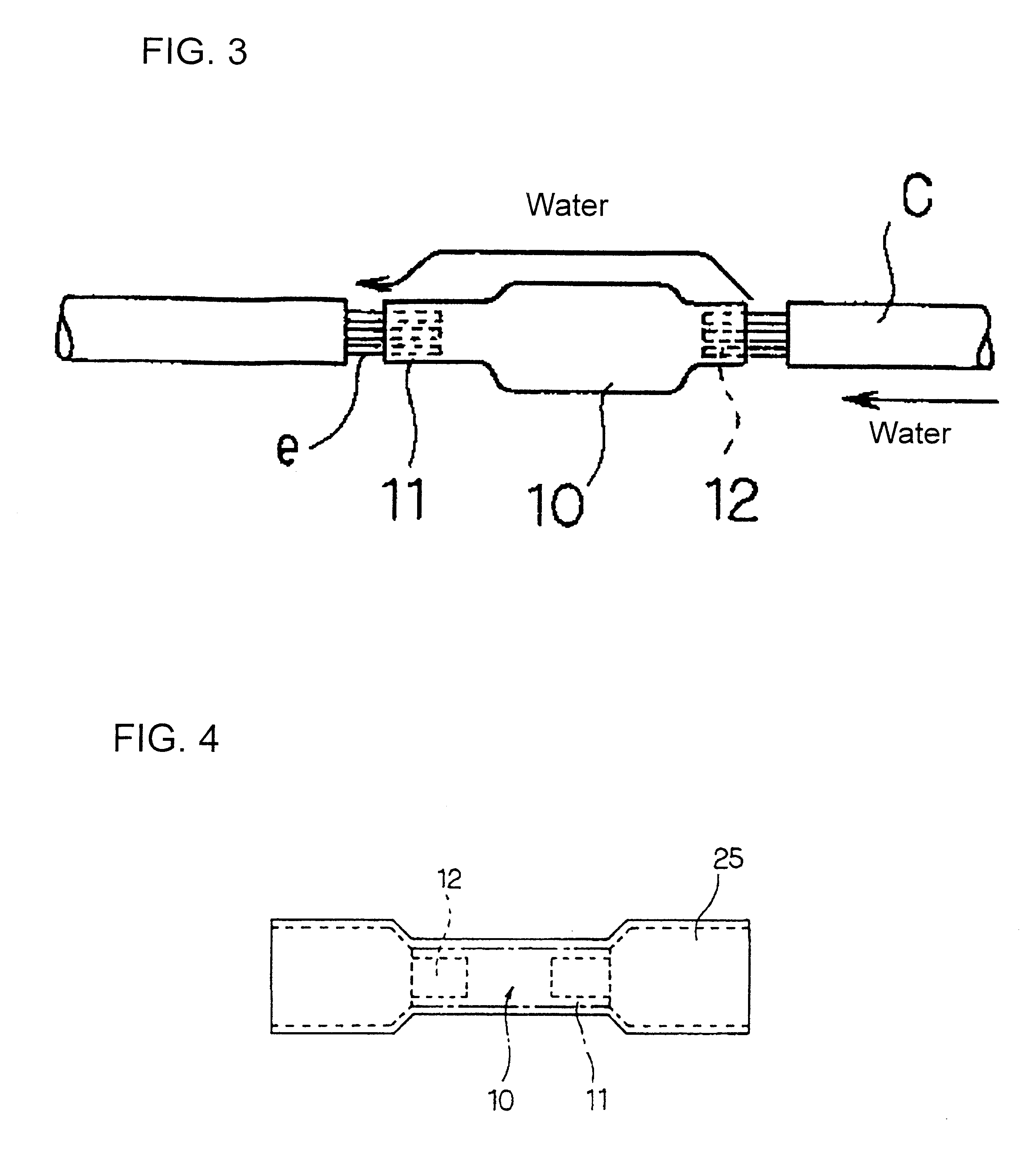
a technology for connecting terminals and electric cables, which is applied in the direction of connection end caps, connection formation by deformation, coupling device connections, etc., can solve the problems of electrical short circuit, water readily entering the end of the electric cable and flowing downstream

Inactive Publication Date: 2003-12-09
SUMITOMO WIRING SYST LTD
View PDF16 Cites 42 Cited by
  • Summary
  • Abstract
  • Description
  • Claims
  • Application Information

AI Technical Summary

Benefits of technology

The solid liquid-tight body between the crimping portions of the crimping terminal is different from a conventional tubular terminal for connection. Water cannot enter the crimping terminal and the body made of a conductive material can electrically connect the electric cables. Consequently, the crimping terminal can interrupt water, which enters an electric cable at an up stream-side and flows in the cable. The crimping terminal also can prevent water from further flowing in an electric cable at a down stream-side.
In this embodiment of the invention, it is possible to bring the tubular member into close contact with the outer surfaces of the crimping portions and ends of the electric cables by heating the tubular member with a dryer or the like. Accordingly, it is possible to prevent the water, which is interrupted in the electric cable, from coming out onto the outer surfaces of crimping portions and entering an electric cable at a down stream side from an electric cable at an up stream side

Problems solved by technology

These connections involve different handlings due to differently designed wiring paths and costs for the respective electric cables C.
However, water readily enters an end of the electric cable and flows downstream due to capillary phenomenon.
In the worst case, this may cause an electrical short-circuit.
FIG. 7 is a side elevation view of a conventional terminal, illustrating a problem therein.

Method used


Image

  • Crimping terminal for connection between electric cables
  • Crimping terminal for connection between electric cables
  • Crimping terminal for connection between electric cables

Examples


Embodiment Construction

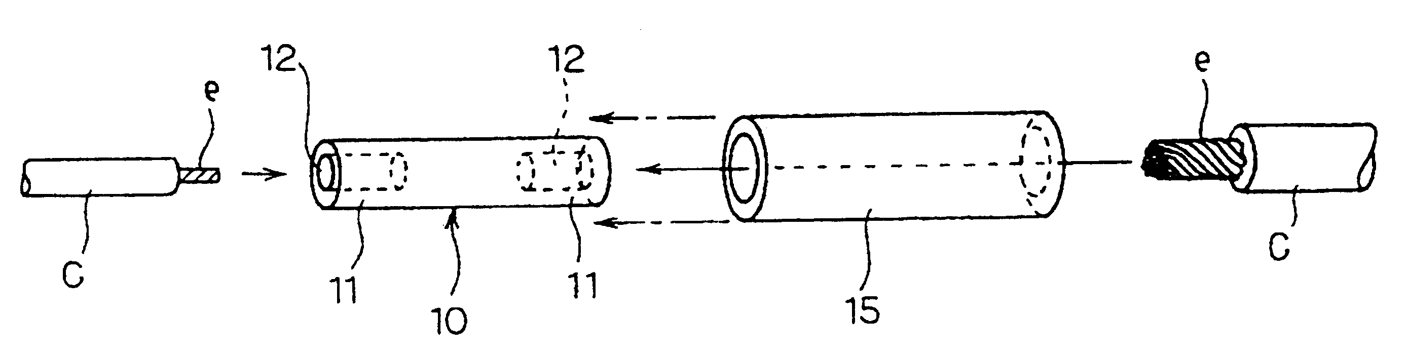
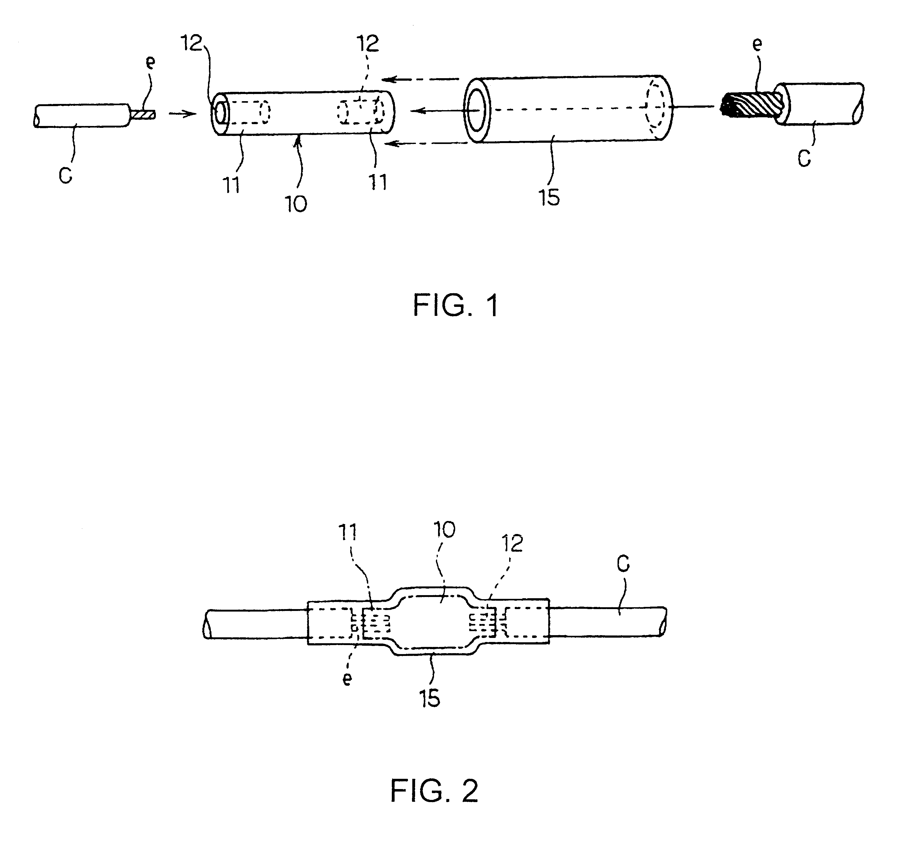
A crimping terminal in accordance with the subject invention is identified by the numeral 10 in FIG. 1. The crimping terminal 10 is made of the same material as that of a conventional crimping terminal and is formed into a cylindrical configuration. Crimping portions 11 are defined at opposite ends of the crimping terminal 10, and insertion holes 12 with bottoms are formed coaxially in the respective crimping portions 11. The insertion holes 12 are dimensioned to receive each end of core wires e in an electric cable C. The crimping terminal 10 can electrically connect ends of the electric cables C by stripping an end of a sheath of the electric cable C to expose ends of the core wires e in the cable C, inserting the exposed ends of the core wires e into the insertion hole 12, and clamping and deforming peripheries of the crimping portions 11 by means of a crimping tool (not shown). The crimping terminal 10 may be produced by means of a machining process or a molding process in consi...


PUM

PropertyMeasurementUnit
conductiveaaaaaaaaaa
heat-shrinkableaaaaaaaaaa
electricalaaaaaaaaaa

Abstract

The present invention discloses a crimping terminal which can interrupt immersion of water in an electric cable and maintain a waterproof function of a mating member, thereby enhancing reliability of connection between electric cables. A crimping terminal 10 is provided on each of cylindrical opposite ends with a crimping portion 11 having an insertion hole 12 with a bottom, which receives core wires e in an electric cable C. A solid body is formed between the crimping portions 11 in a liquid-tight manner. Preferably, the crimping terminal 10 is used together with a thermal-shrinkable tube 15 having an adhesive on its inner surface so that the thermal-shrinkable tube 15 comes into close contact with outer surfaces of the crimping portions and electric cables C.

Description

1. Field of the InventionThis invention relates to a crimping terminal for connection between electric cables, and more particularly, the invention relates to a crimping terminal that can prevent moisture from coming into clearances between core wires in the electric cables.2. Description of the Related ArtPrior art electric cables that extend from electric devices easily can be coupled to or disconnected from each other by attaching a connector to each of the electric cables and coupling and disconnecting the connectors. Some prior art connectors are constructed to prevent the intrusion of water. For example, as shown in FIG. 5, waterproof connectors 1 and 2 are attached to the electric cables C. The FIG. 5 assembly also includes a non-waterproof connector 3 that is attached to an electric cable C Additionally, a so-called round terminal 4 or the like is attached to an electric cable C to perform direct screw connection. These connections involve different handlings due to differen...

Claims


Application Information

Patent Timeline
Patent Type & Authority Patents(United States)
IPC IPC(8): H01R4/10H01R4/18H01R13/52H01R4/22
CPCH01R4/183H01R13/5208Y10T29/49199Y10T29/49194Y10T29/49195Y10T29/49202
Inventor ITO, AKIRA
Owner SUMITOMO WIRING SYST LTD
Why Eureka
Try Eureka