Compact planar antenna

a planar antenna and antenna technology, applied in the direction of resonant antennas, antenna earthings, elongated active element feeds, etc., can solve the problem of too large antennas of some applications

Inactive Publication Date: 2003-12-16
LAIRD CONNECTIVITY LLC
View PDF4 Cites 26 Cited by
  • Summary
  • Abstract
  • Description
  • Claims
  • Application Information

AI Technical Summary

Benefits of technology

to provide a compact planar antenna which is small enough to be used in most applications.

Problems solved by technology

Although the antenna of the '344 patent performs very well, it has been found that the antenna thereof is too large for some applications.

Method used


Image

  • Compact planar antenna
  • Compact planar antenna

Examples


Embodiment Construction

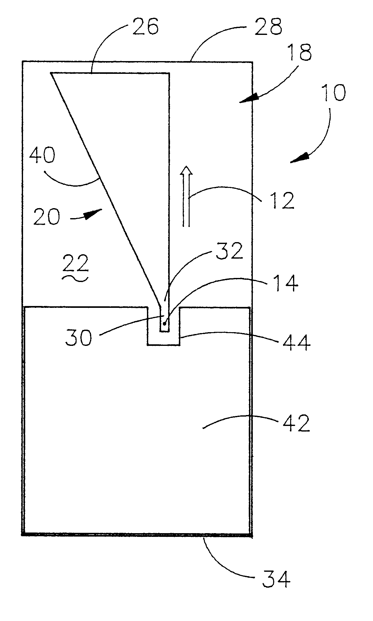
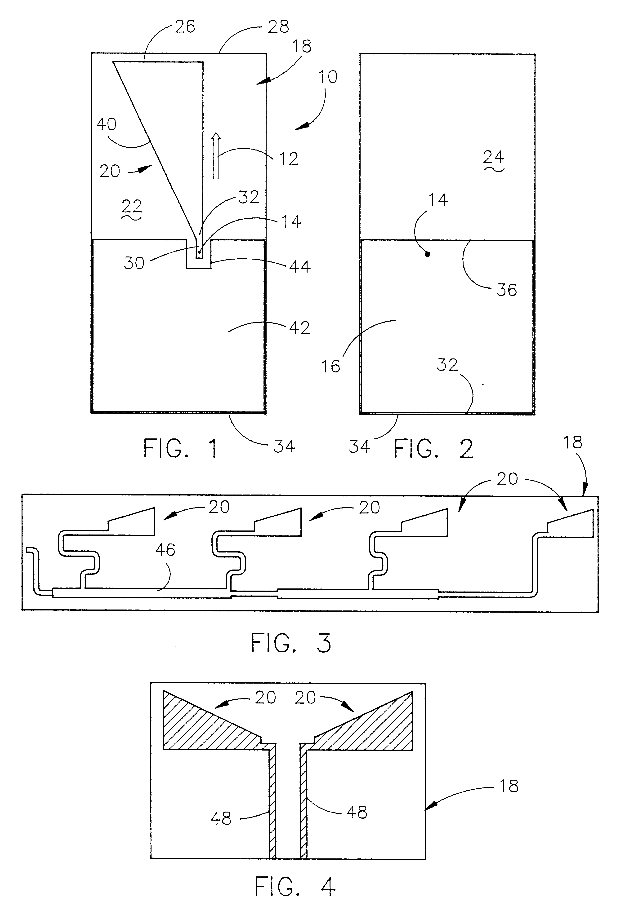
FIG. 1 is a top view, i.e., a view from the radiating element side, of an antenna 10 in accordance with this invention wherein a final protective non-conductive plastic coating has not been applied to the antenna, and wherein the centrally located long-axis of antenna 10 is shown by arrow 12. FIG. 2 is a bottom view, i.e., a view from the ground plane element side, of an antenna 10. The numeral 14 refers to a through hole which extends through the ground plane 16, substrate 18, and the antenna element 20 to facilitate the connection of a feed cable to the antenna.

Without limitation thereto, in a preferred embodiment of the invention, antenna 10 is formed from a relatively thin commercial PCB laminate substrate such as glass epoxy. The top and bottom flat surfaces 22 and 24 of substrate 18 carry a thin layer, coating, or film of a metal such as copper. Copper-clad substrate 18 is processed, for example, by using well-known masking and etching techniques, to provide (1) a first metal ...


PUM


Abstract

A compact planar antenna is disclosed wherein a radiating element in the shape of a right triangle is formed on a substrate. A ground plane may be positioned on one or both sides of the substrate. In one embodiment, the radiating elements are positioned on the substrate in groups of two or more in close proximity to one another. In another embodiment, the radiating elements are arranged in an array.

Description

1. Field of the InventionThis invention relates to a compact planar antenna for wireless communication devices such as cellular telephones, PCMCIA cards, etc. More particularly, the compact planar antenna of this invention enables the antenna to be used in pairs or in linear array situations.2. Description of the Related ArtA number of small patch or planar antennas have been previously provided which were generally useful for their limited intended purposes. In U.S. Pat. No. 6,157,344 (the '344 patent), a patent owned by the assignee of the instant invention, a small indoor / outdoor, shock tolerant, flat panel, transmit / receive antenna is described. U.S. Pat. No. 6,249,254 (the '254 patent), a patent owned by the assignee of the instant invention, describes the method of making the invention of the '344 patent. The disclosure of the '344 and '254 patents are included herein by reference thereto. In the antenna of the '344 patent, the radiating element thereof is triangular-shaped, o...

Claims


Application Information

Patent Timeline
Patent Type & Authority Patents(United States)
IPC IPC(8): H01Q1/38H01Q9/04H01Q9/40H01Q1/22H01Q9/28
CPCH01Q1/38H01Q9/40H01Q9/28
Inventor ZINANTI, MICHAEL D.FRENCH, SHANNA CARROLLBANCROFT, RANDY C.LAWSON, JR., KENNETH T.BATEMAN, BLAINE R.
Owner LAIRD CONNECTIVITY LLC
Why Eureka
Try Eureka