Multi-band planar antenna

Inactive Publication Date: 2003-12-09
LAIRDTECH INC
View PDF8 Cites 47 Cited by
  • Summary
  • Abstract
  • Description
  • Claims
  • Application Information

AI Technical Summary

Benefits of technology

to provide a compact, multi-band planar antenna whi

Problems solved by technology

Additionally, multi-band antennas have often been more complex in structure than single-band antennas, hence multi-band antennas have been of higher cost than single band antennas.
While the antenna of the '525 patent performs exceedingly well and has been successfully commercialized, it is relatively large a

Method used


Image

  • Multi-band planar antenna
  • Multi-band planar antenna

Examples


Embodiment Construction

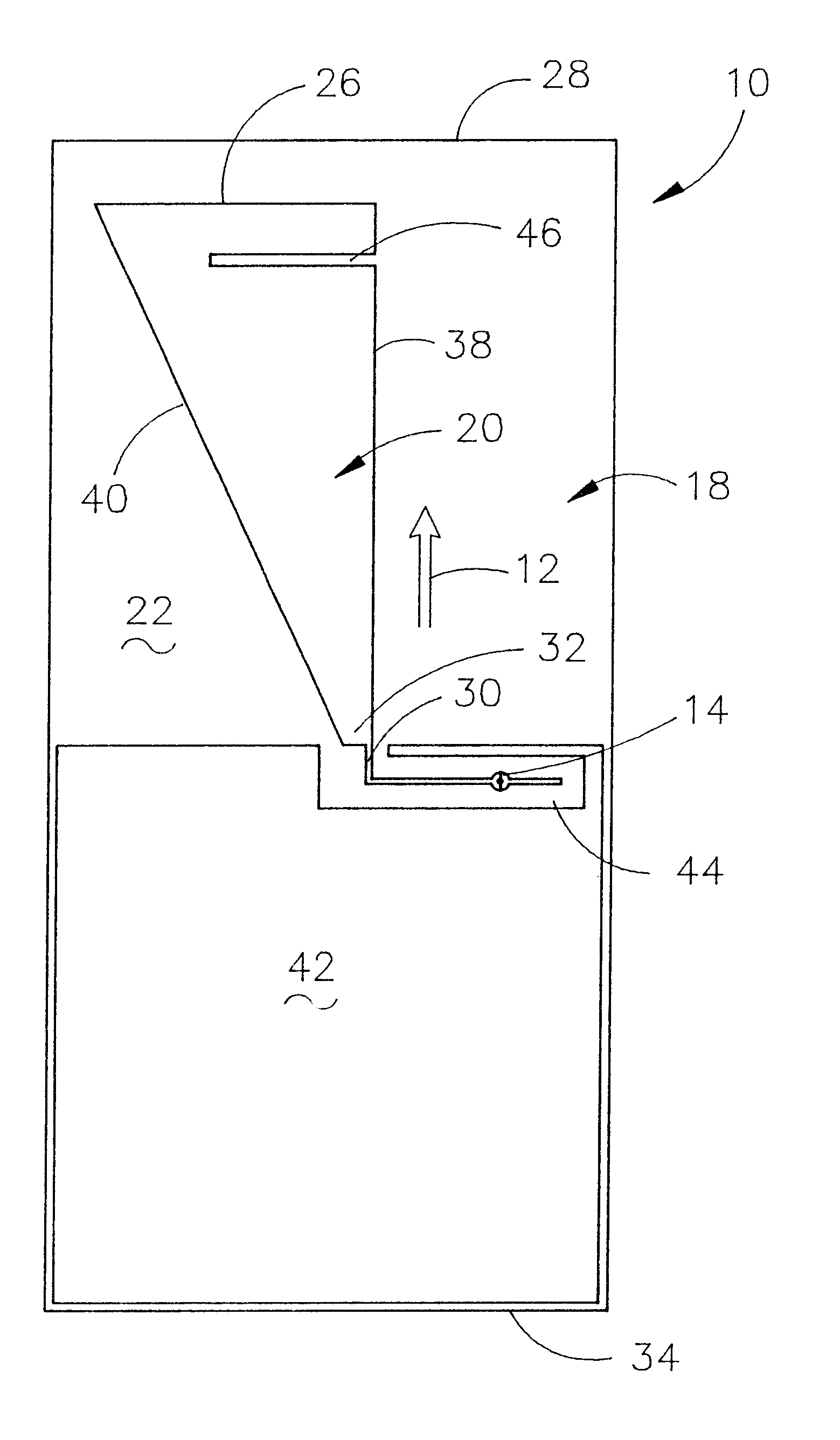
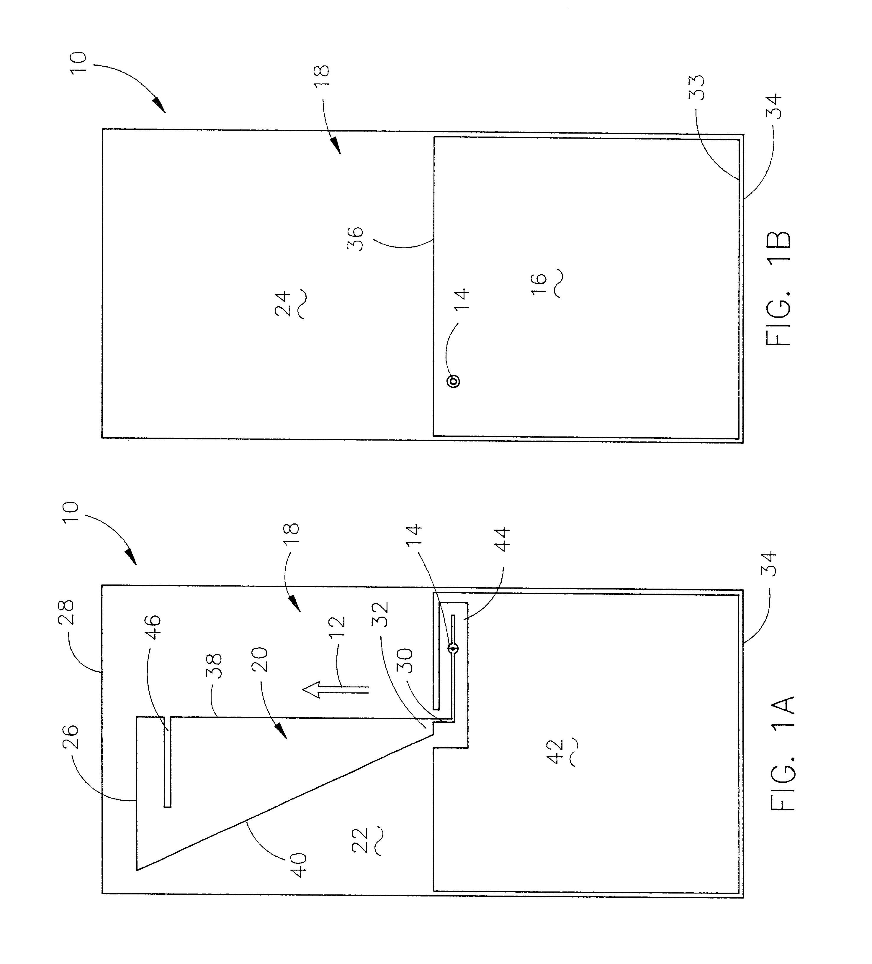
FIG. 1A is a top view, i.e., a view from the radiating element side, of an antenna 10 in accordance with this invention wherein a final protective non-conductive plastic coating has not been applied to the antenna, and wherein the centrally located long-axis of antenna 10 is shown by arrow 12. FIG. 1B is a bottom view, i.e., a view from the ground plane element side, of an antenna 10. The numeral 14 refers to a through hole which extends through the ground plane 16, substrate 18, and the antenna element 20 to facilitate the connection of a feed cable to the antenna.

Without limitation thereto, in a preferred embodiment of the invention, substrate 18 of antenna 10 is formed from a relatively thin commercial PCB laminate substrate such as glass epoxy. The top and bottom flat surfaces 22 and 24 of substrate 18 carry a thin layer, coating, or film of a metal such as copper. Copper-clad substrate 18 is processed, for example, by using well-known masking and etching techniques, to provide ...


PUM


Abstract

A compact planar antenna is disclosed wherein a radiating element in the shape of a right triangle is formed on a substrate. A ground plane may be positioned on one or both sides of the substrate. A slot extends into the radiating element from one side thereof.

Description

Your Petitioners, RANDY C. BANCROFT, a citizen of the Unit States and a resident of the State of Colorado, whose residence and mailing address is 2837 Perry Street, Denver, Colo. 80212; MICHAEL D. ZINANTI, a citizen of the United States and a resident of the State of Colorado, whose residence and mailing address is 4147 Ingalls Court, Wheat Ridge, Colo. 80033; KENNETH T. LAWSON, JR., a citizen of the United States and a resident of the State of Colorado, whose residence and mailing address is 1249 James Circle, Lafayette, Colo. 80026; SHANNA CARROLL FRENCH, a citizen of the United States and a resident of the State of Colorado, whose residence and mailing address is 4432 South Beech Way, Morrison, Colo. 80465; and BLAINE R. BATEMAN, a citizen of the United States and a resident of the State of Colorado, whose post office address is 593 Juniper Court, Louisville, Colo. 80027, pray that Letters Patent may be granted to them for the improvement inA MULTI-BAND PLANAR ANTENNAAs set forth...

Claims


Application Information

Patent Timeline
IPC IPC(8): H01Q1/38H01Q9/04H01Q9/40H01Q5/00H01Q1/24
CPCH01Q1/243H01Q9/40H01Q9/0407H01Q1/38
Inventor BANCROFT, RANDY C.ZINANTI, MICHAEL D.LAWSON, JR., KENNETH T.FRENCH, SHANNA CARROLLBATEMAN, BLAINE R.
Owner LAIRDTECH INC
Why Eureka
Try Eureka