Waste water lifting installation

a technology for lifting and removing waste water, which is applied in the direction of using liquid separation agents, rod connections, containers, etc., can solve the problems of difficult access to water lifting installation and difficult access to waste water lifting installation, and achieve the effect of convenient opening for maintenance purposes

Active Publication Date: 2014-02-04
GRUNDFOS HLDG
View PDF11 Cites 0 Cited by
  • Summary
  • Abstract
  • Description
  • Claims
  • Application Information

AI Technical Summary

Benefits of technology

[0006]It is therefore the object of the invention, to provide a waste water lifting installation which is easier to open for maintenance purposes, even if the waste water lifting installation is placed where it is difficultly accessible, in particular directly behind a WC.
[0009]The flange plate, on a first side edge which faces the middle region of the waste water lifting installation, according to the invention, is releasably fixed with a single locking element, on the collection container. The middle region of the waste water lifting installation is that region which is the most difficult to access, in particular if the waste water lifting installation is set up behind a WC. For this reason, it is advantageous if only a single locking element is arranged in this region and must be released for removing the flange plate. I.e. several poorly accessible screws on this side edge do not have to be released, but rather the flange plate may be easily released from the collection container by way of releasing a single locking element at this side edge.
[0014]Thereby, the locking element is preferably rotatable between a locking position and a released position about an angle of smaller than 360° and preferably smaller or equal to 180°. I.e., a relatively small rotational movement or pivot movement is sufficient, in order to move the locking element between the locking position and the released position. The locking element may thus be released and locked much more easily than a conventional screw which needs to be rotated several times, i.e. a multiple of 360°.
[0018]The second engagement element may preferably be formed on or in an insert which is connected, preferably screwed, to the collection container or the flange plate. Such an insert has the advantage that an undercut or pocket may be more easily formed in the collection container, since these elements do not need to be designed as one piece with the collection container, but may be formed by a separate component. The manufacture is therefore simplified. Moreover, the engagement element may be exchanged when damaged, as the case may be.
[0019]In a particular embodiment of the invention, the first and the second engagement element may comprise corresponding threads which may be brought into engagement with one another. Thereby, the threads preferably have such a pitch, that a small rotation of the locking element is already sufficient, in order to bring the thread of the first and second engagement into and out of engagement. In this case, the locking element with the thread is preferably provided with a hand grip, so that it may be easily manually locked and released.

Problems solved by technology

With this set-up arises the problem that the waste water lifting installation is difficultly accessible for maintenance purposes.
Several screws are to be released for this, wherein screws which in particular are situated in the middle region of the waste water lifting installation are very difficult to access with the arrangement behind a WC.

Method used


Image

  • Waste water lifting installation
  • Waste water lifting installation
  • Waste water lifting installation

Examples


first embodiment

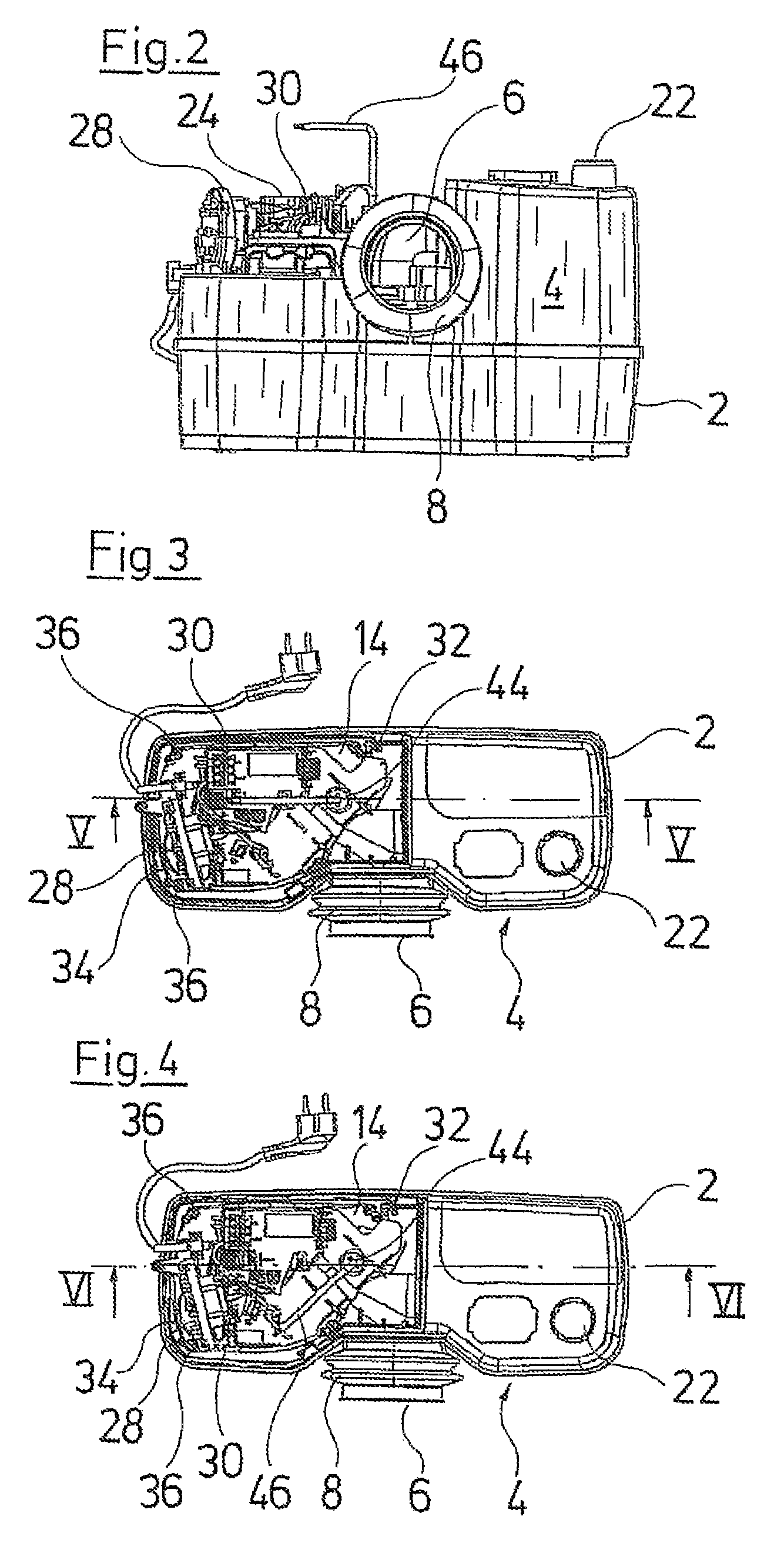
[0044]The first side edge 32 however as a rule is difficultly accessible, so that here, according to the invention, a different fastening is envisaged. Here, one does without the normal standard screws. According to the invention which is described in more detail by way of FIGS. 2-7, instead of this, a locking element 40 in the form of a pivotable bar 40 is provided. This locking element 40 is arranged on the flange plate 14. The pivotable bar 40 is designed as a radially projecting locking projection which extends radially outwards from a sleeve 42 rotatable about the pivot axis S. The upper side of the sleeve 42 is closed off by a slotted plug 44 which is connected to the sleeve 42 in a rotationally fixed manner. A spanner 46 for rotating the sleeve 42 may engage into the slot of the plug 44. Thereby, the spanner 46 is designed angled, so that it may be inserted and rotated even when little free space is available above the waste water lifting installation.

[0045]The bar 40 in the ...

third embodiment

[0048]the invention is explained by way of FIGS. 13-16. In this embodiment, the flange plate 14 has a locking projection 58 which extends to the middle of the waste water lifting installation outwards past the first side edge 32 in the horizontal direction. A pivotable lever 60 is arranged on the collection container 2 and is pivotable about a horizontally extending pivot axis A. In the locked position, the lever 60 is pressed downwards and engages over the locking projection 58 at its upper side, so that the locking projection 58 with the flange plate 14 may not be moved upwards. In the unlocked position, the lever 60 is pivoted such that the space above the locking projection 58 is released and the locking projection 58 with the flange plate 14 may be removed to the top. The lever 60 is curved in a manner such that in the locked position, it bears or snugly lies on the outer side of the arch-shaped wall 10. Thereby, as is to be seen in FIG. 14, the lever 60 is so wide between the ...


PUM

PropertyMeasurementUnit
angleaaaaaaaaaa
angleaaaaaaaaaa
anglesaaaaaaaaaa

Abstract

A waste water lifting installation has a collection container and a pump assembly. The pump assembly is fastened on a flange plate which closes an opening on the upper side of the collection container. The flange plate, on a first side edge which faces the middle region of the waste water lifting installation, is releasably fixed on the collection container with a single locking element.

Description

CROSS REFERENCE TO RELATED APPLICATIONS[0001]This application claims the benefit of priority under 35 U.S.C. §119 of European Patent Application 11185758.7 filed Oct. 19, 2011, the entire contents of which are incorporated herein by reference.FIELD OF THE INVENTION[0002]The invention relates to a waste water lifting installation with a collection container and with a pump assembly, wherein the pump assembly is fastened on a flange plate which closes an opening on an upper side of the collection container.BACKGROUND OF THE INVENTION[0003]Waste water lifting installations are applied, in order to lift or pump waste water which occurs below the level of a waste water conduit or a sewage system, to the level of a waste water conduit which is situated higher. This for example is the case with cellars or basement when discharges of sanitary objects are situated below the sewage system.[0004]For this, waste water lifting installations are known, which comprise a collection container, into ...

Claims


Application Information

Patent Timeline
Patent Type & Authority Patents(United States)
IPC IPC(8): E03D1/00
CPCE03F5/22E03F11/00Y10T137/86035Y10T403/32459Y10T137/85978
Inventor CASALINI, LUCAIACOPONI, ALESSANDROSCHOMACKER, RALF
Owner GRUNDFOS HLDG
Why Eureka
Try Eureka