Tire comprising a measurement device

a technology of measurement device and axis spherical, which is applied in the field of spherical tires, can solve the problems of inability to manufacture various parts of the sensor by microelectronic techniques, lack of sensitivity along the axis of the spherical tires,

Inactive Publication Date: 2003-12-23
MICHELIN RECH & TECH SA
View PDF6 Cites 82 Cited by
  • Summary
  • Abstract
  • Description
  • Claims
  • Application Information

AI Technical Summary

Benefits of technology

The application of the force to the shank at a certain distance from the deformable element and the anchoring of the deformable element at several points make it possible to determine not only the force component in a plane transverse to the shank but also the force component along the axis of the shank.

Problems solved by technology

The major disadvantage of this structure is its lack of sensitivity along the axis of the shank.
The various parts of the sensor cannot be assembled by microelectronic techniques.

Method used


Image

  • Tire comprising a measurement device
  • Tire comprising a measurement device
  • Tire comprising a measurement device

Examples


Embodiment Construction

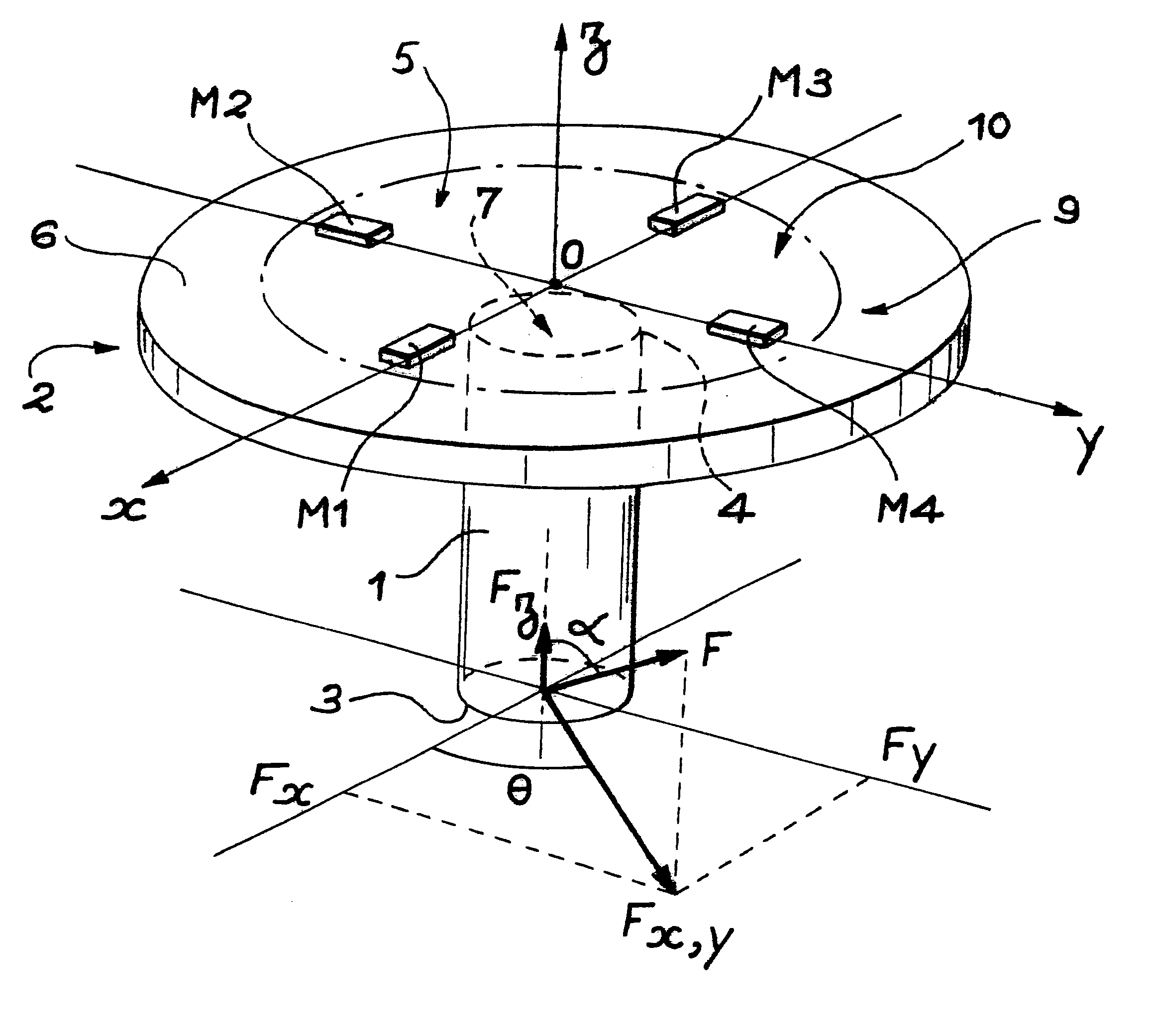
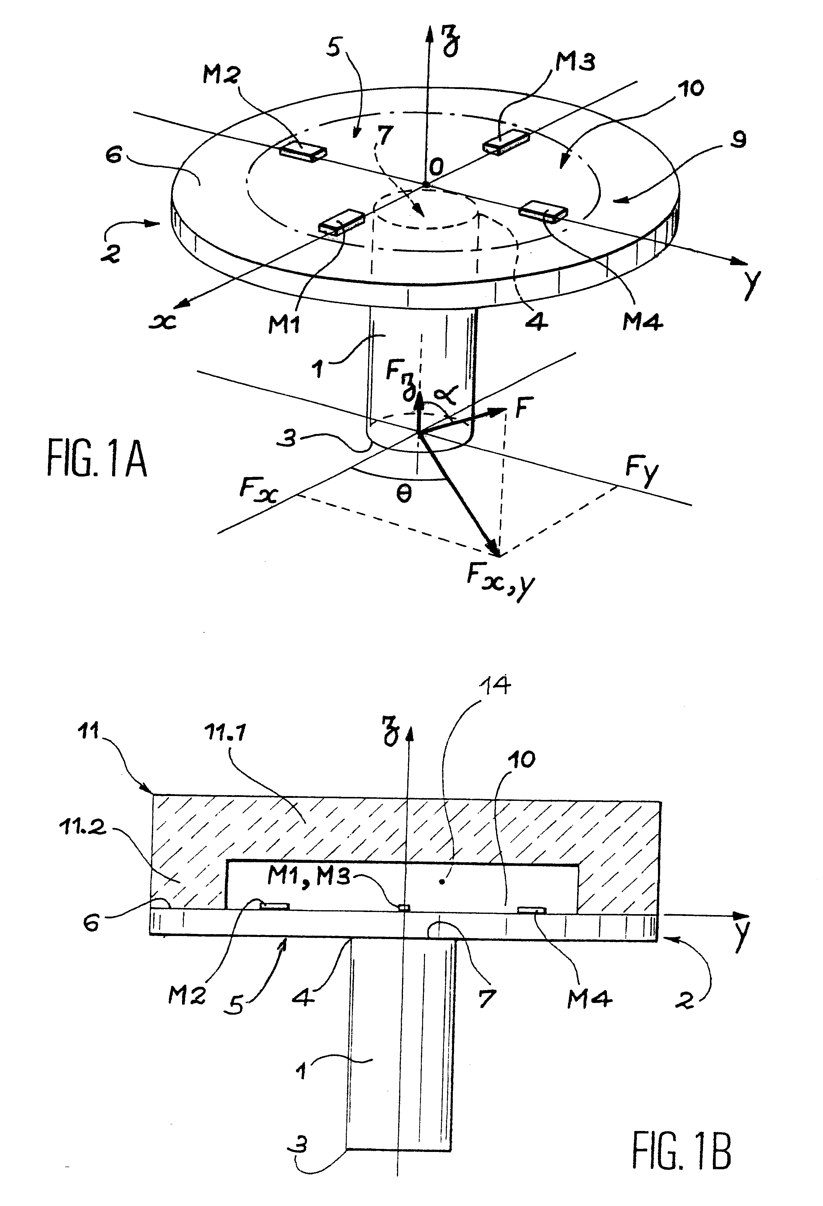
With reference to FIGS. 1A and 1B, the force sensor shown is of the nail type. It has a rigid shank 1 with a head 2 at one end. The shank 1 is directed along the z-axis. It has a free end 3 and its other end 4 is attached to the head 2. At the level of the head 2, the perpendicular axes (x, y) define a plane perpendicular to the z-axis.

The shank 1 is intended to be displaced by a force F which, in the most general case, is decomposed into a component .sub.F(x, y) in the plane (x, y) and a component F.sub.z along the z-axis. It is taken that the force F is directed at an angle .alpha. relative to the z axis and that the component F.sub.(x, y) is directed at an angle .theta. relative to the x-axis. Such a sensor enables the various components of the force F to be determined.

The point of application of the force F is a distance away from the end 4 of the shank 1 at which it is attached to the head 2.

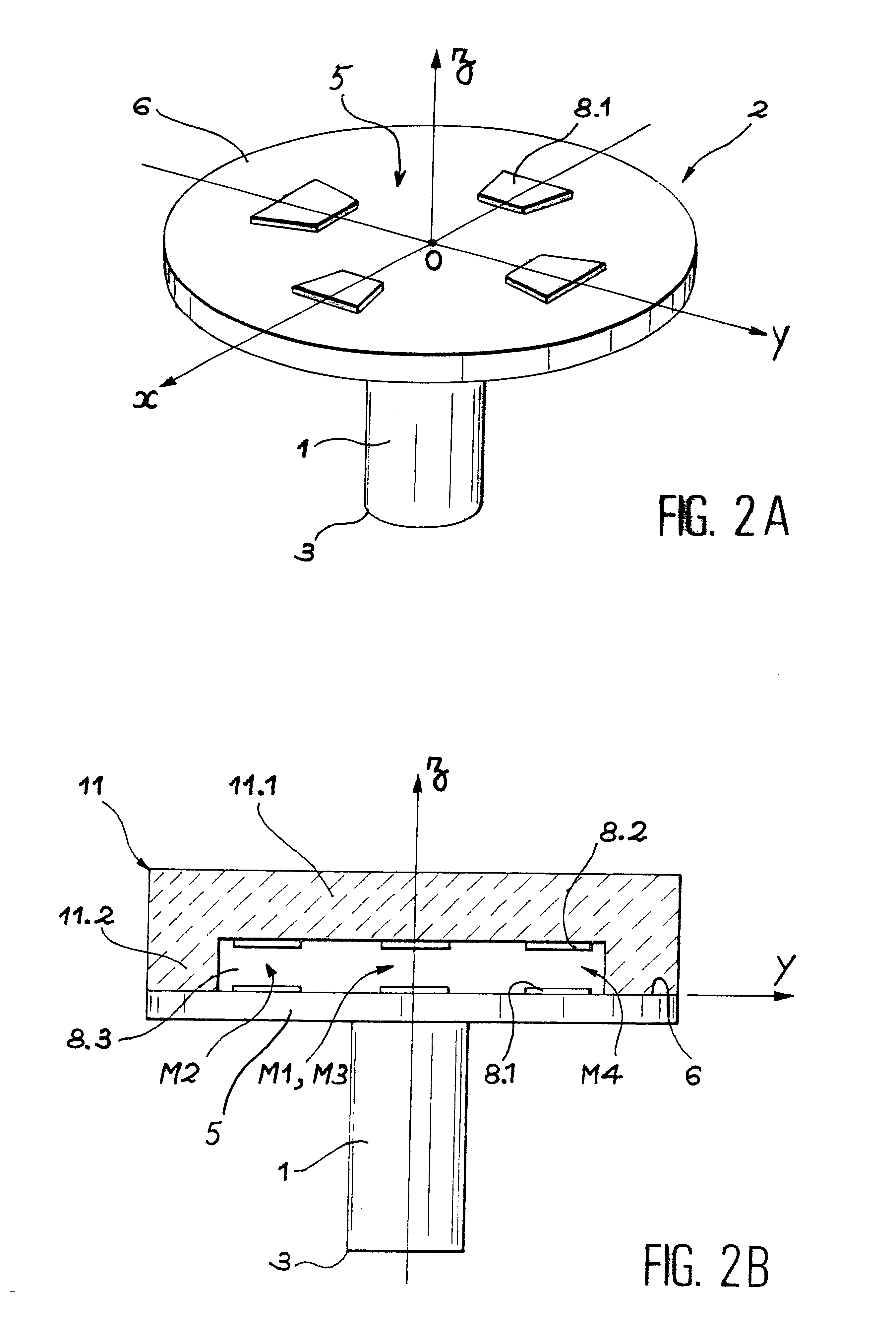
The head 2 of the force sensor comprises an element 5 which can deform when the shank 1...


PUM

PropertyMeasurementUnit
forceaaaaaaaaaa
stressaaaaaaaaaa
piezoelectricaaaaaaaaaa

Abstract

A tire includes a nail-type force sensor embedded, for example, in an isolated element such as a tread pattern block (T112). The sensor comprises a rigid shank (1) designed to be acted upon by the force to be determined and a head (2). The head (2) comprises an element attached to the shank (1) capable of being deformed when the shank is displaced. This deformable element carries means to measure the deformation and comprises anchoring points which have a position relative to the shank (1) at rest and which essentially maintain that position when the shank (1) is displaced.

Description

1. Technical Field of the InventionThe present invention concerns a tire equipped with a nail-type force measurement device.2. The Related ArtU.S. Pat. No. 5,864,056 discloses a nail-type force sensor for tires, wherein the shank of the sensor is a flexible blade fitted with two strain gauges mounted back to back and the head of the sensor comprises at least two rigid discs transverse to the shank, separated by a tube orientated in the direction of the shank.The major disadvantage of this structure is its lack of sensitivity along the axis of the shank. It can only pick up the components of a force located in a plane transverse to the axis of the shank. Now, it is important to know all of the components of the force, so that with one and the same sensor a lack of grip, for example, can be detected.A nail-type force sensor for tires is also known from patent application EP-A-O 937 615. This nail-type sensor has a rigid shank, one end of which is free while the other end is attached t...

Claims


Application Information

Patent Timeline
Patent Type & Authority Patents(United States)
IPC IPC(8): G01L5/22G01L5/16G01M17/02B60C19/00
CPCB60C23/0493G01L5/161B60C11/243G01L5/223G01M17/02G01L5/162
Inventor POULBOT, VALERYREY, PATRICE
Owner MICHELIN RECH & TECH SA
Why Eureka
Try Eureka