Electric starter device for an internal combustion engine

a technology of an internal combustion engine and an electric starter, which is applied in the direction of engine starters, engine emergency protection arrangements, etc., can solve the problems of affecting the switching performance of the bimetallic switch in the critical (hot) region, is either very difficult or even impossible in engineering terms, and is difficult to achieve. severe hysteresis, and the effect of large switching capacity

Inactive Publication Date: 2003-12-30
ROBERT BOSCH GMBH
View PDF7 Cites 12 Cited by
  • Summary
  • Abstract
  • Description
  • Claims
  • Application Information

AI Technical Summary

Problems solved by technology

It has been found that in electric starters, the hottest points, with the greatest potential risk, are the carbon brushes and the commutator.
Disposing the bimetallic switch in the region of the critical (hottest) points, however, is either very difficult or even impossible in engineering terms.
Such bimetallic switches are indeed simple in design and in their principle of operation, but they are relatively large.
Moreover, their switching performance involves to severe hysteresis.

Method used


Image

  • Electric starter device for an internal combustion engine
  • Electric starter device for an internal combustion engine

Examples


Embodiment Construction

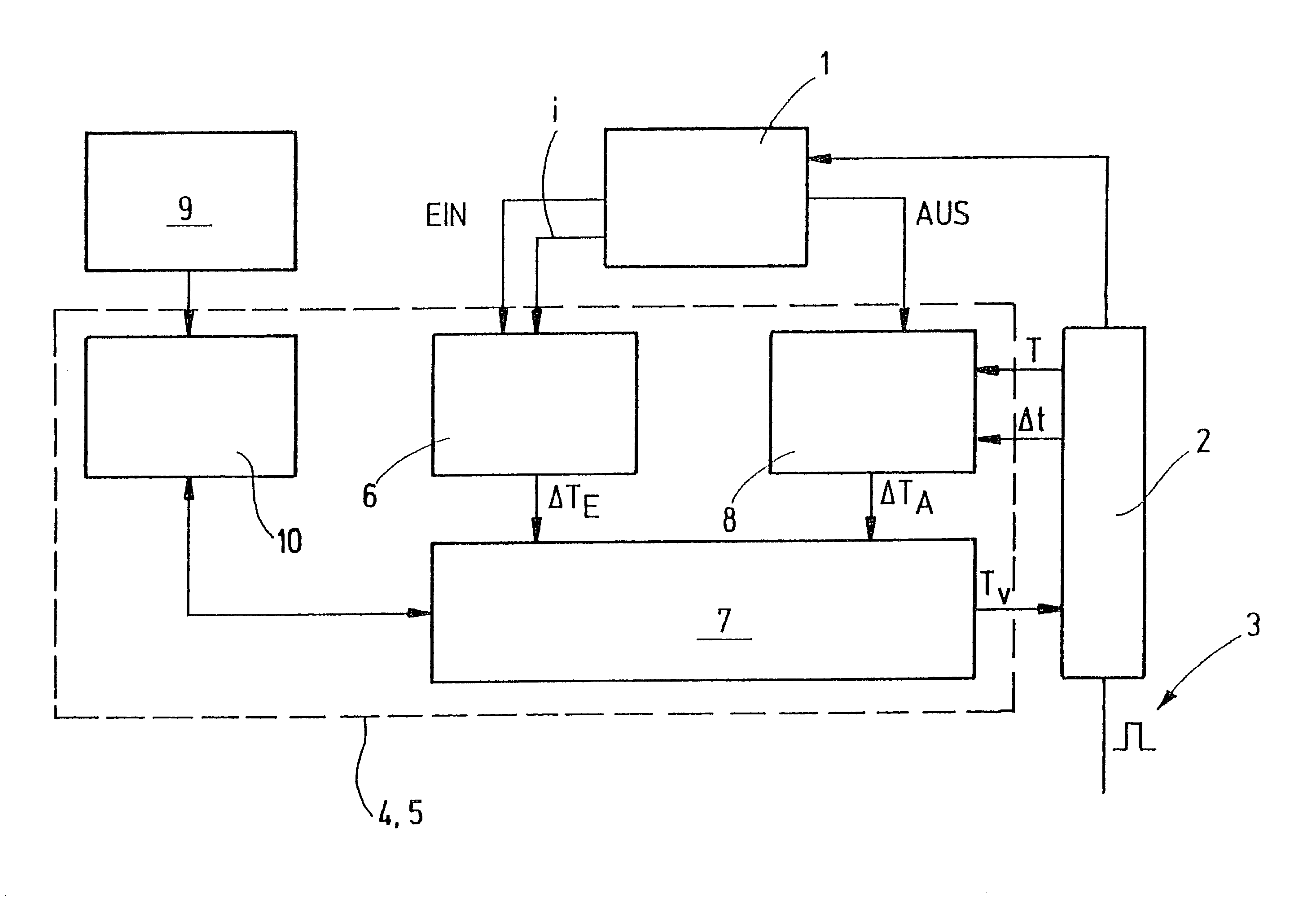
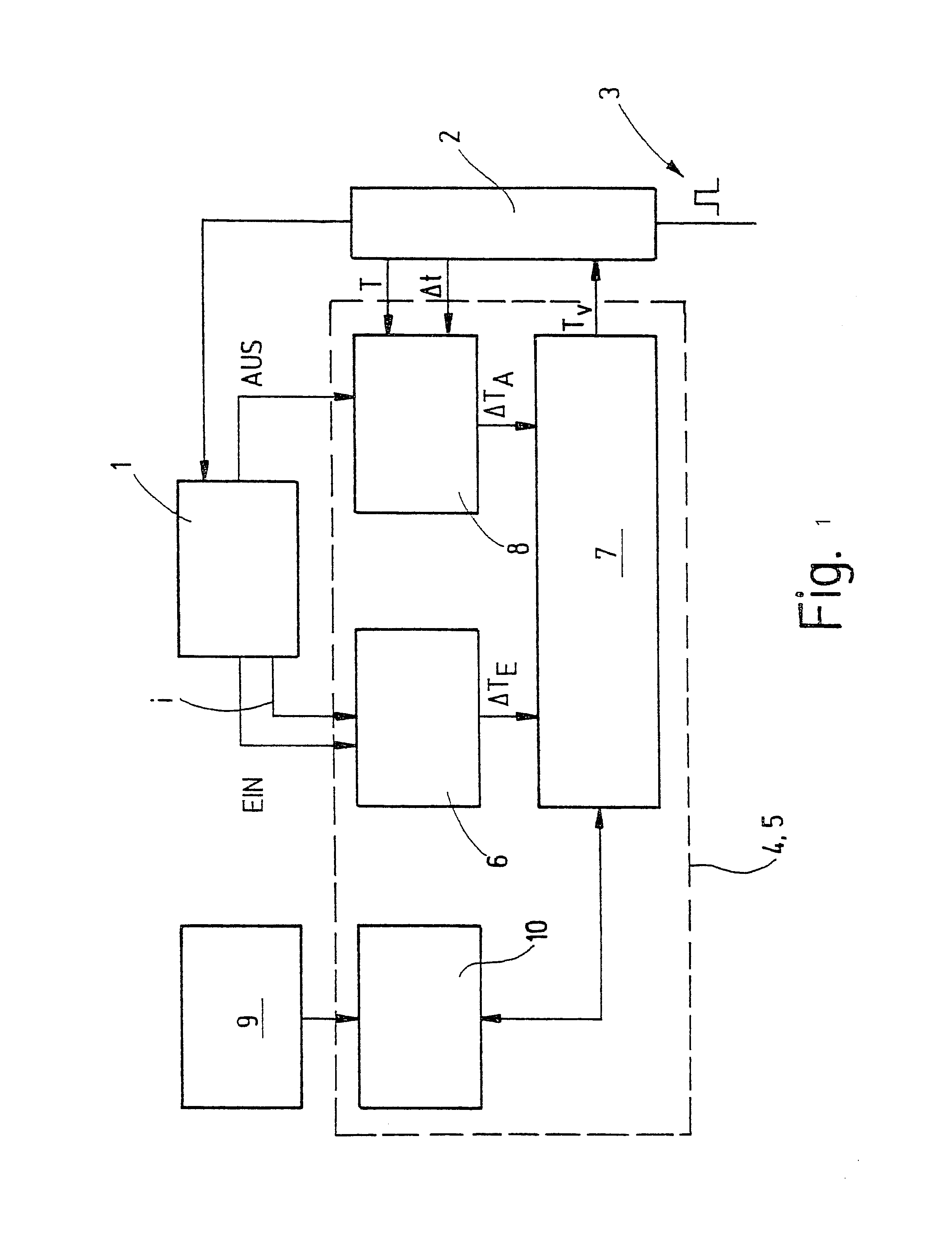
In the block circuit diagram, the electric starter for an internal combustion engine is identified by reference numeral 1. The starter is preferably a so-called tip starter, which is triggerable via a control unit that in response to a control pulse 3 actuates the starter 1 until such time as the engine (not shown) that is to be started has reached a predetermined rpm. After that, the control unit turns the starter 1 off again, to protect it from damage. The control unit 2 preferably has a protective function to guard against misuse of the starter 1, so that the starter 1 cannot be activated while the engine is running, for instance.

The block circuit diagram also shows a thermal monitoring device 4 for the thermal monitoring protection of the starter 1. The monitoring device 4 preferably forms a unit with the control unit 2 and in particular is integrated with the control unit 2.

The monitoring device is embodied as a device 5 for ascertaining a virtual operating temperature of the s...


PUM


Abstract

The invention relates to an electric starter for an internal combustion engine, having a thermal monitoring protector (4) for turning the starter (1) off when its limit operating temperature is reached. The starter is characterized by a device (5) for ascertaining a virtual operating temperature (TV); the device (5) ascertains the virtual operating temperature (TV) as a function of at least one operating parameter that affects the operating temperature of the starter (1).

Description

The invention relates to an electric starter for an internal combustion engine.PRIOR ARTIn luxury cars, so-called tip starters are preferably used, which automatically perform the starting operation for the internal combustion engine by means of a starting pulse. The result is a decoupling between the selection of starting and the starting event itself. In tip-starters, the starting event is thus controlled electronically and is ended at the earliest possible moment, for instance once the engine is at a predeterminable minimum rpm. Since the starting event is not successful in all cases, provision must be made to assure that the starting event will not be continued indefinitely, both to protect the starter battery and to avoid a thermal overload on the electric starter. It has been found that in electric starters, the hottest points, with the greatest potential risk, are the carbon brushes and the commutator.To make a thermal monitoring protection for such starters feasible, it is k...

Claims


Application Information

Patent Timeline
Patent Type & Authority Patents(United States)
IPC IPC(8): F02N11/10F02N11/00F02N11/08H02H6/00H02H5/04
CPCF02N11/10H02H6/005F02N2200/044F02N2200/122F02N2300/2008F02N2200/045
Inventor SEILS, WOLFGANGACKERMANN, MANFRED
Owner ROBERT BOSCH GMBH
Why Eureka
Try Eureka