Thermal imaging based monitoring system

a monitoring system and thermal imaging technology, applied in the field of thermal imaging based monitoring systems, can solve the problems of limiting the use of high-performance, long-wave imaging to high-value instruments, such as aerospace, military, or large-scale commercial applications

Inactive Publication Date: 2017-05-25
SEEK THERMAL
View PDF10 Cites 10 Cited by
  • Summary
  • Abstract
  • Description
  • Claims
  • Application Information

AI Technical Summary

Problems solved by technology

Such thermal imaging sensors have long been expensive and difficult to produce, thus limiting the employment of high performance, long wave imaging to high value instruments, such as aerospace, military, or large scale commercial applications.

Method used


Image

  • Thermal imaging based monitoring system
  • Thermal imaging based monitoring system
  • Thermal imaging based monitoring system

Examples


Embodiment Construction

[0031]One or more embodiments described herein may provide for installing a thermal monitoring system for both enclosed and open spaces conveniently with little or no infrastructure modification.

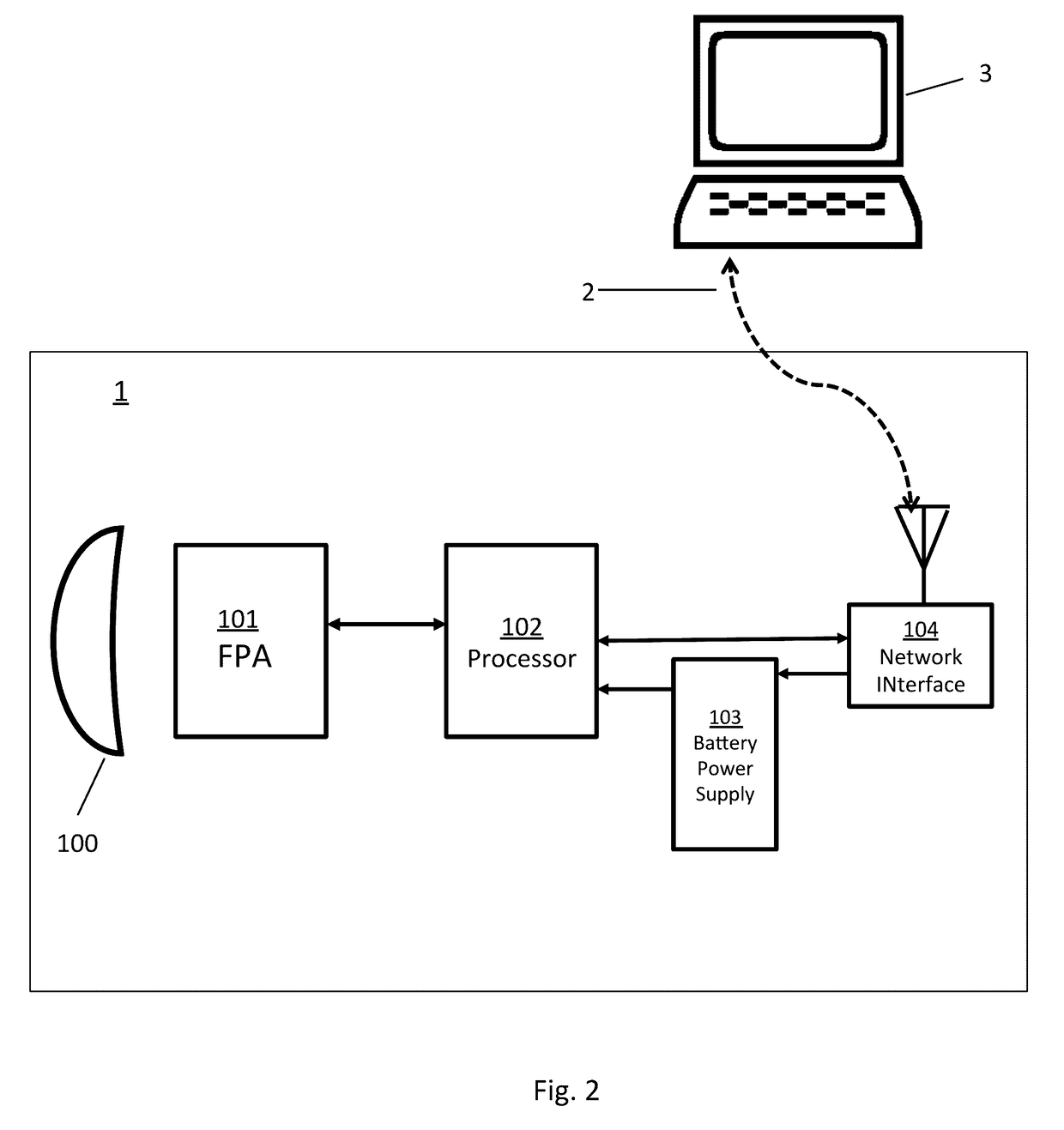
[0032]One or more embodiments described herein may provide for inexpensive, battery powered thermal imaging monitors with long battery life.

[0033]One or more embodiments described herein may provide convenient interfacing of the thermal imaging monitors to the internet for remote control and data acquisition.

[0034]One or more embodiments described herein may provide for a variety of environmental reporting including temperature alerts for specific regions of the space along with thermal images and temperature maps if desired.

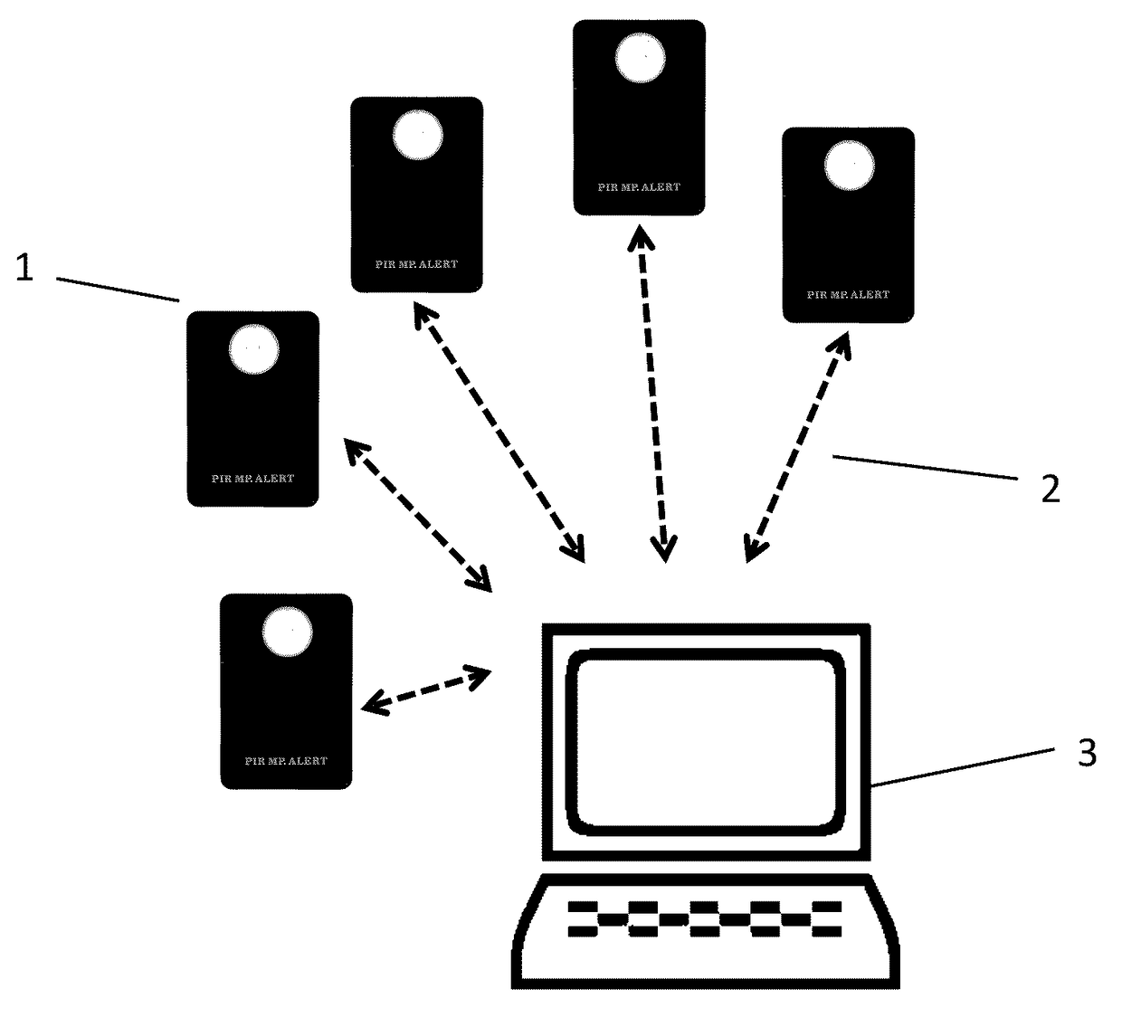
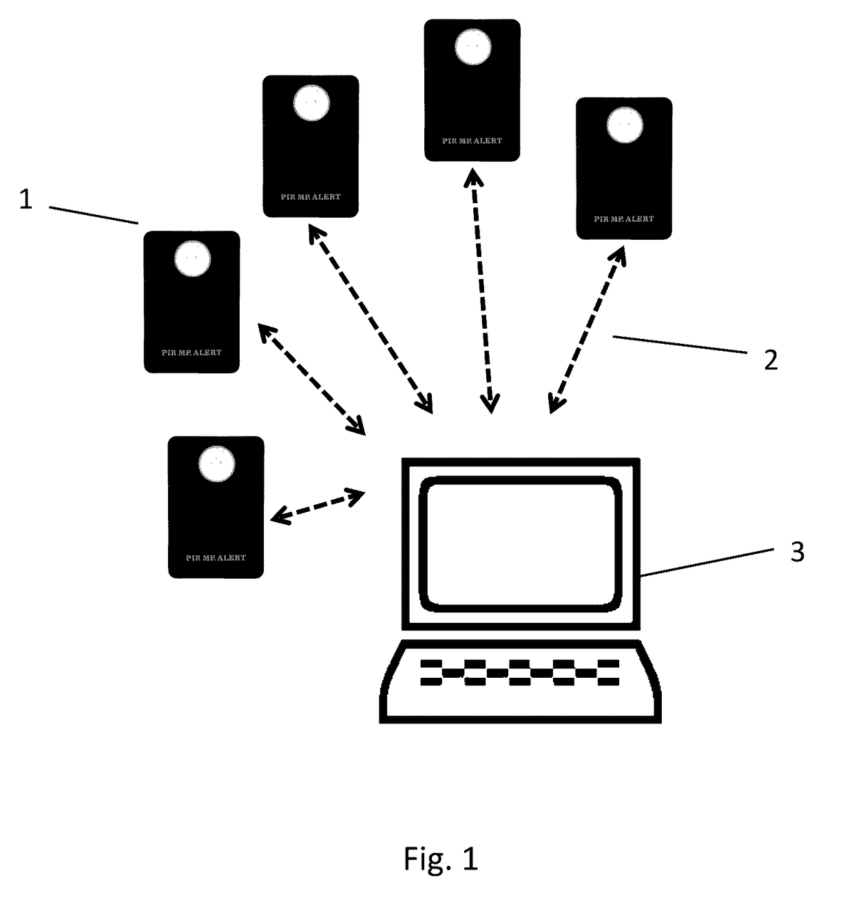
[0035]One or more embodiments described herein may allow for environmental monitors from multiple users to access server function on a network such as the internet, and for users to access their monitors and monitor data through accounts.

[0036]The environmental monitor s...


PUM


Abstract

Systems and methods for thermal monitoring of a Field of View (FOV), including at least one thermal imaging module. The thermal imaging module includes an Infrared Focal Plane Array (IR FPA) and optics for producing a thermal image of a scene including a portion of the FOV, at least one processor, a battery based power supply controlled by the processor, and a network interface to the processor. Also included is an application executing on the processor, configured to put the module into a low power mode, wherein only minimal timing and network interface functions are operable, for at least one of predetermined intervals or in response to a network wake-up command, power up module and acquire thermal image data of the scene, segment the image of the scene into two or more regions, perform thermographic analysis to determine the temperature of each region, return to low power mode and repeat, and at least one system controller in communication with the modules over the network.

Description

[0001]The specification relates to thermal monitoring of a space and in particular to one or more networked thermal imaging modules.[0002]The increasing availability of high performance, low cost uncooled infrared imaging devices, such as bolometer focal plane arrays, is enabling the design and production of mass produced, consumer oriented IR cameras capable of quality thermal imaging. Such thermal imaging sensors have long been expensive and difficult to produce, thus limiting the employment of high performance, long wave imaging to high value instruments, such as aerospace, military, or large scale commercial applications. Mass produced, inexpensive thermal imagers may enable new methodologies for thermal monitoring of enclosed or non-enclosed spaces.BRIEF DESCRIPTION[0003]In some embodiments, system or methods may be provided for one or more battery operated thermal imaging modules mounted to observe part or all of a space, and configured to operate in a low power quiescent mode...

Claims


Application Information

Patent Timeline
Patent Type & Authority Applications(United States)
IPC IPC(8): H04N5/33G06K9/00H04N7/18H04N5/232G06V10/22
CPCH04N5/33H04N5/23241H04N7/181G06K9/00536G06K9/00771G06V20/52G06V10/22H04N23/661H04N23/651H04N23/90
Inventor PARRISH, WILLIAM J.HENRY, BLAKE
Owner SEEK THERMAL
Why Eureka
Try Eureka