

In-cabinet thermal monitoring method and system
a thermal monitoring and in-cabinet technology, applied in the field of thermal monitoring of electrical equipment, can solve the problems of requiring a trained operator, requiring a large number of thermographic imaging limitations, and a large number of equipment limitations
- Summary
- Abstract
- Description
- Claims
- Application Information
AI Technical Summary
Benefits of technology
Problems solved by technology
Method used
Image

Examples
Embodiment Construction
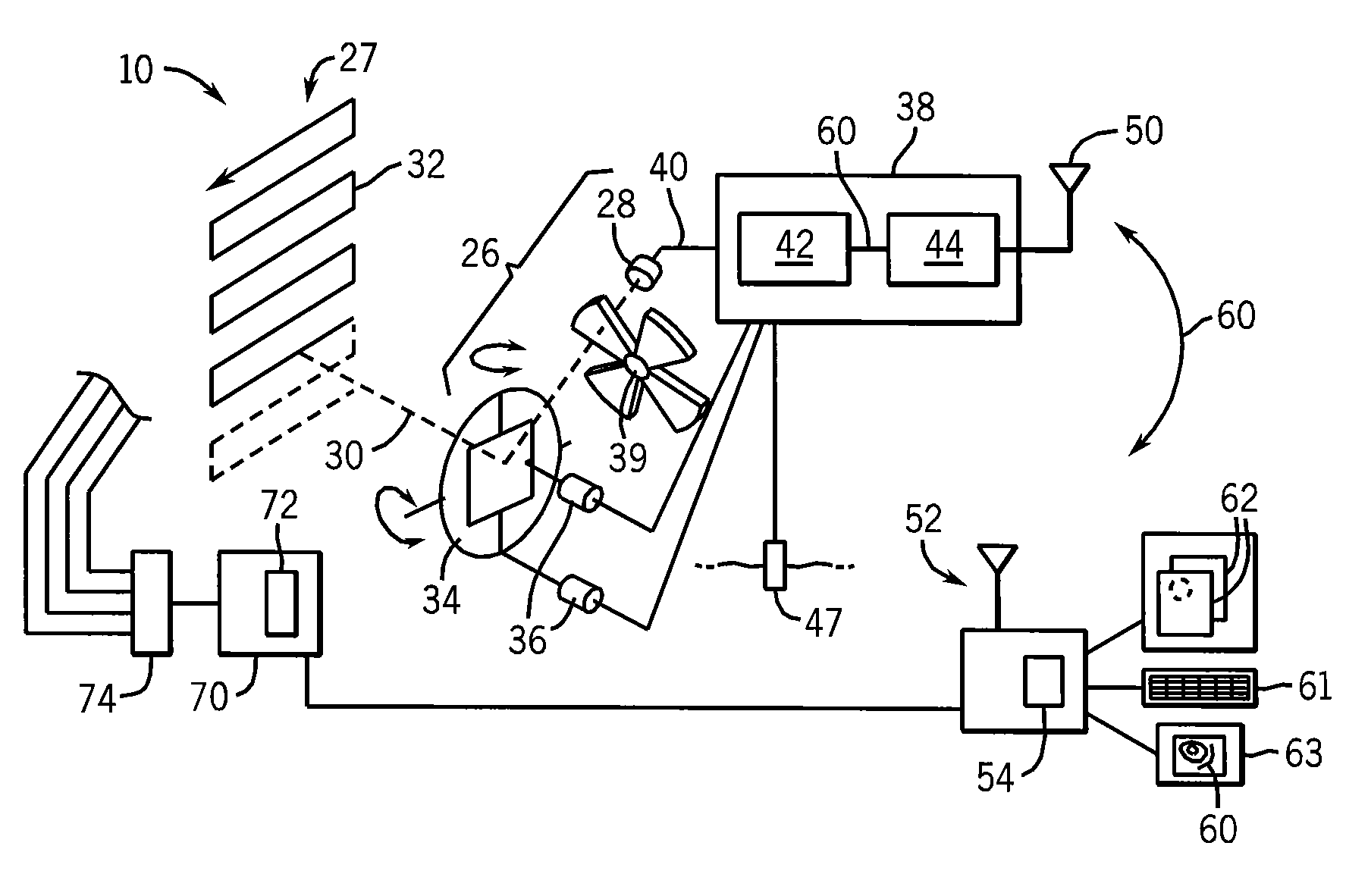
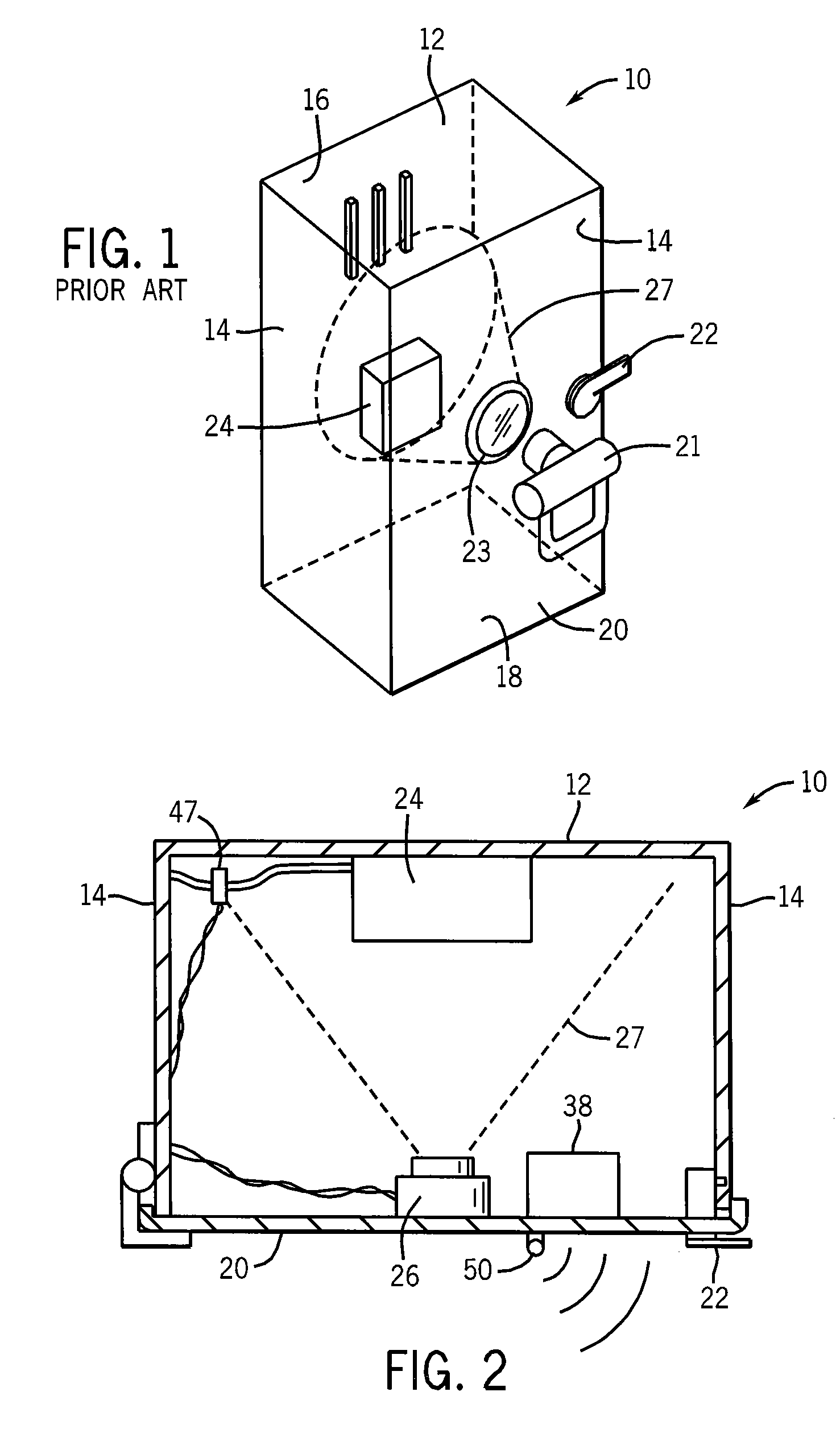
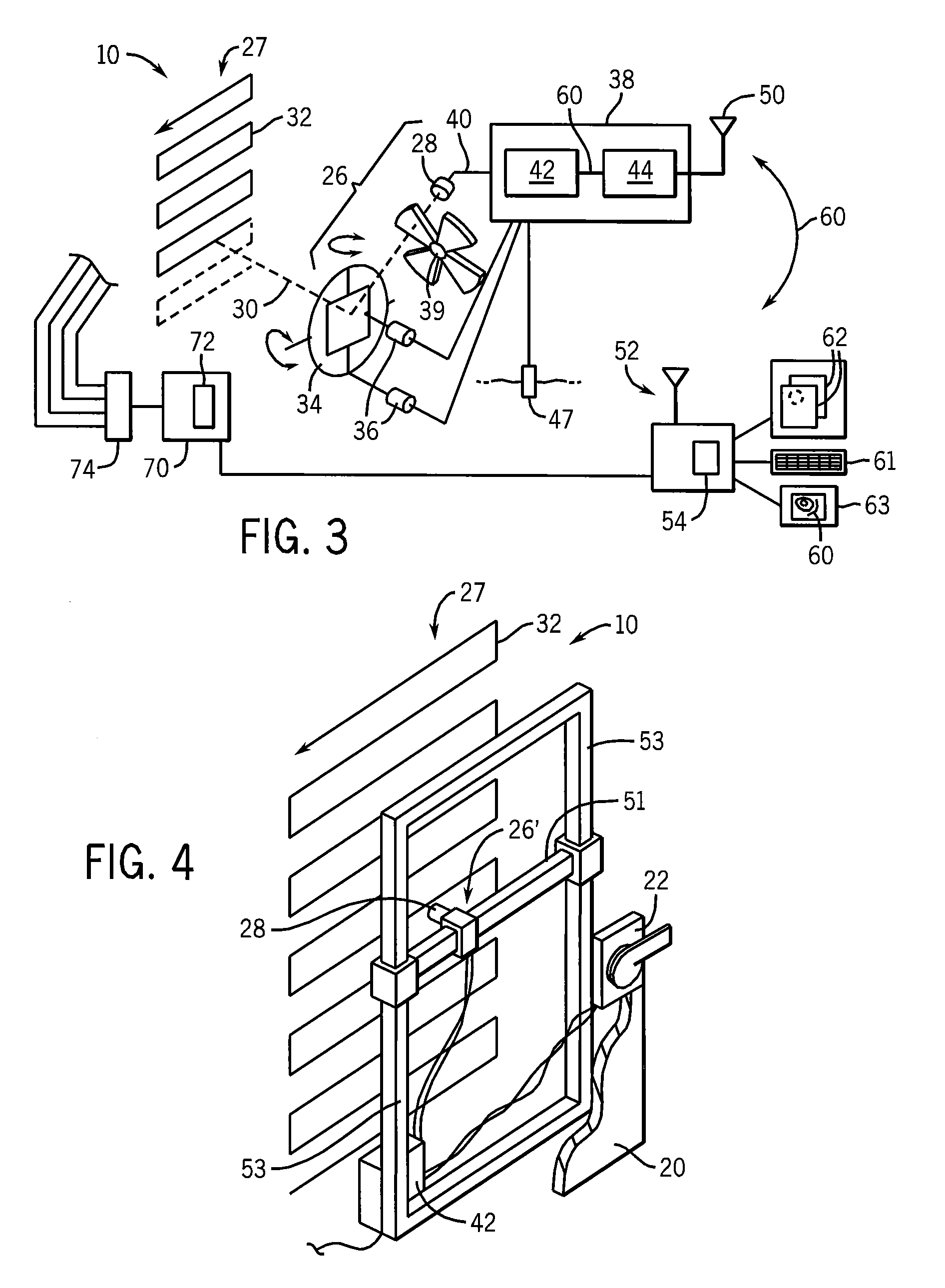
Referring now to FIG. 1, a switchgear cabinet 10 may have a rear vertical wall providing a mounting panel 12 surrounded by forwardly extending sidewalls 14, top wall 16 and bottom wall 18 to provide a protected volume enclosed by front door 20 opposite the mounting panel 12. Typically the cabinet 10 is constructed of steel panels to provide a strong and fire resistant housing.
The front door 20 may be opened and closed for access to the enclosed volume in the cabinet 10 by means of a handle 22 which may turn to lock the cabinet 10 and which may be connected to an electrical interlock (not shown) or the like to disconnect power from the cabinet 10 when the door 20 is opened. The door 20 may support a port 23 providing either an infrared transparent window or an openable shutter allowing viewing of internal components by a thermographic camera 21 by a human operator while providing maximum protection to the operator.
The cabinet 10 may include multiple electrical components 24, for exam...
PUM
| Property | Measurement | Unit |
|---|---|---|
| electrical | aaaaa | aaaaa |
| volume | aaaaa | aaaaa |
| light frequency | aaaaa | aaaaa |
Abstract
Description
Claims
Application Information