Thermal monitoring of a converter

A technology for converters and monitoring signals, which is applied in the direction of emergency protection circuit installations in response to unexpected changes, testing of electrical devices and electrical components during transportation, and can solve problems such as critical driving conditions

Active Publication Date: 2014-04-09
VALEO EAUTOMOTIVE GERMANY GMBH
View PDF5 Cites 11 Cited by
  • Summary
  • Abstract
  • Description
  • Claims
  • Application Information

AI Technical Summary

Problems solved by technology

This could lead to a critical driving situation

Method used


Image

  • Thermal monitoring of a converter
  • Thermal monitoring of a converter
  • Thermal monitoring of a converter

Examples


Embodiment Construction

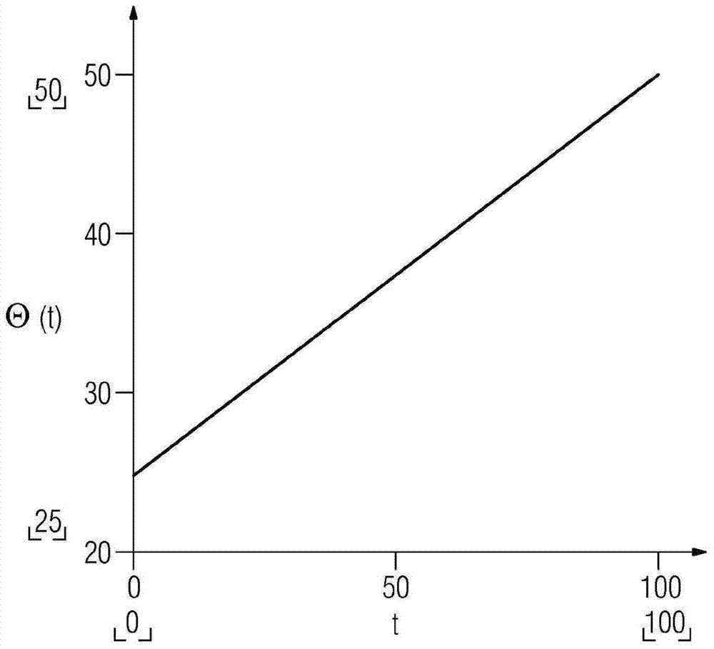
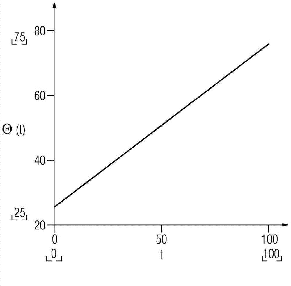
[0021] The time constant, ie the time it takes for the temperature of the converter to heat up to a predetermined temperature value, differs significantly with and without effective water cooling. For certain general applications, the time constant can be easily determined and stored in the converter or its monitoring system. A thermal model of the converter temperature can be constructed using this time constant.

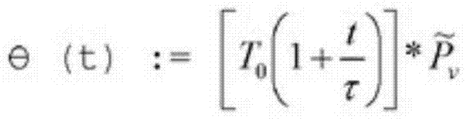
[0022] An important factor in the thermal model is the power loss of the converter. This power loss refers to that part of the power that is finally converted into heat in the converter. This power loss can be determined according to the following formula:

[0023] P V = (1-η)P ges

[0024] Among them, η is equivalent to the efficiency of the converter, that is, the quotient of output power and input power. P ges Equivalent to the input power, which is the total power flowing into the converter. This power P ges Usually derived from the values ​​used to re...


PUM


Abstract

The thermal monitoring of a converter for an electric motor of a vehicle should be improved. Therefore, the invention relates to a method in which the temperature of the converter is measured. In addition, the output power of the converter is determined. The temperature of the converter is estimated by means of a thermal model of the converter having the output power as an input variable. The estimated temperature is compared with the measured temperature, and a corresponding monitoring signal is provided. Thus, a deviation of the measured temperature for the calculated temperature and thus a corresponding error in the cooling system can be detected even in the partial-load range.

Description

technical field [0001] The invention relates to a method for thermal monitoring of a converter of an electric motor of a vehicle, wherein the temperature of the converter is measured. Furthermore, the invention relates to a monitoring device for thermal monitoring of the above-mentioned converter, which monitoring device has a measuring device for measuring the temperature of the converter. Background technique [0002] Motor vehicle internal combustion engines are usually cooled by means of liquid cooling systems. When the cooling system fails, the temperature of the internal combustion engine rises depending on the load and the ambient conditions. This temperature rise can be observed via display elements in the field of view of the driver. In most cases, when a threshold value is exceeded, an additional acoustic and / or optical signal is generated which draws the driver's attention to the aforementioned situation. The so-called time constant for the approximate temperat...

Claims


Application Information

Patent Timeline
Patent Type & Authority Applications(China)
IPC IPC(8): H02H6/00
CPCG01R31/006H02H7/122H02H6/005
Inventor 安德烈斯·库恩
Owner VALEO EAUTOMOTIVE GERMANY GMBH
Why Eureka
Try Eureka