Aircraft with electric flight controls provided with a fuselage able to deform and vibrate

a technology of electric flight control and fuselage, which is applied in the direction of process and machine control, instruments, navigation instruments, etc., can solve the problems of affecting the performance of said control lines, the unit being subject to the action of the fuselage deformation,

Inactive Publication Date: 2003-12-30
AIRBUS OPERATIONS (SAS)
View PDF9 Cites 12 Cited by
  • Summary
  • Abstract
  • Description
  • Claims
  • Application Information

AI Technical Summary

Problems solved by technology

Of course, as a result, this IRS unit is subjected to the action of the deformations of the fuselage, which deformations occur mainly along the axes of pitch and yaw under the effect of the turning of the control surfaces or the effect of external disturbances.
However, in the case of aircrafts with high longitudinal flexibility, the deformations become greater, which means that it is then necessary to perform extremely intense filtering of said control lines, and this introduces significant phase shifts thereinto and therefore detracts greatly from the performance of said control lines.

Method used


Image

  • Aircraft with electric flight controls provided with a fuselage able to deform and vibrate
  • Aircraft with electric flight controls provided with a fuselage able to deform and vibrate
  • Aircraft with electric flight controls provided with a fuselage able to deform and vibrate

Examples


Embodiment Construction

)

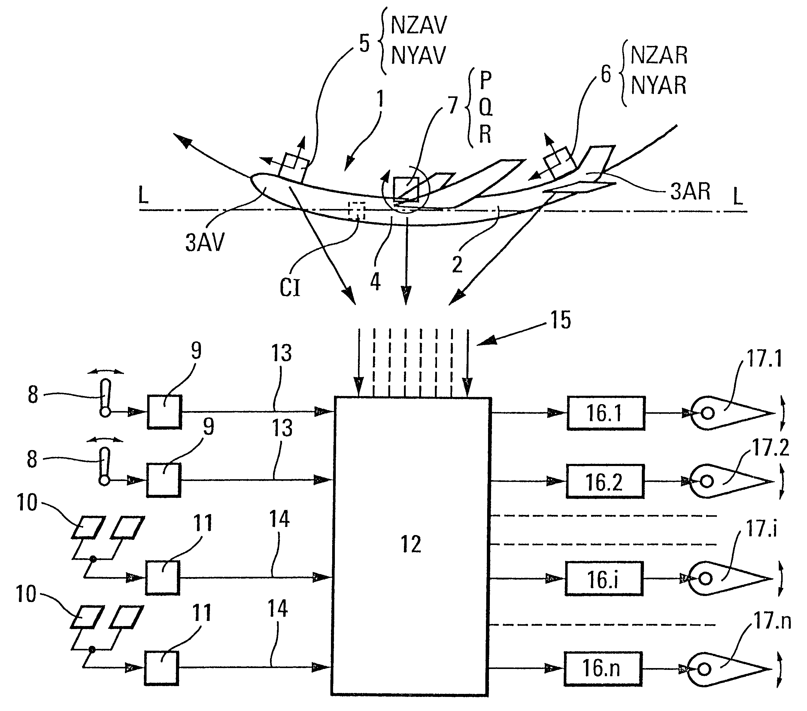
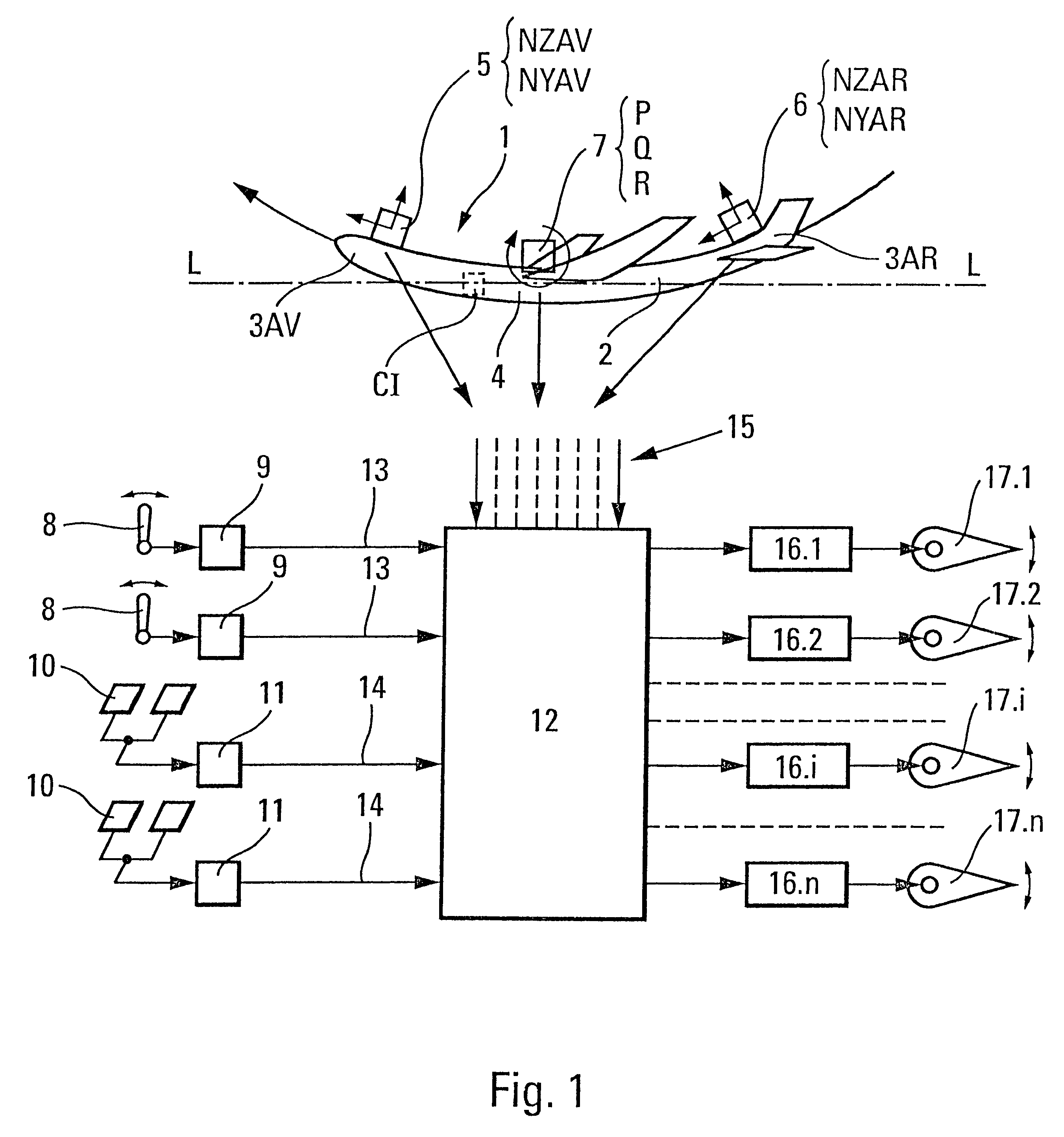
The airplane 1 with high flexibility along its longitudinal axis L--L, shown in FIG. 1, can deform under the effect of the turning of its control surfaces or of external disturbances so that the main deformation of its fuselage 2 in the yaw and pitch axes is very significant at the front 3AV and rear 3AR ends of said fuselage 2 while the center 4 of this fuselage (at which the center of gravity of the airplane 1 is located) deforms little. In addition, the rotation rates associated with the deformations of the fuselage 2 are very small near the center 4 of said fuselage.

As illustrated schematically in FIG. 1, said airplane 1 comprises:

an inertial unit CI, intended for navigation and arranged at any customary and appropriate point on said fuselage 2;

at least one front accelerometer 5 arranged at the front end 3AV;

at least one rear accelerometer 6 arranged at the rear end 3AR; and

at least one gyrometer 7 near the center 4 of said airplane 1.

Of course, although in FIG. 1 the accelerom...


PUM


Abstract

According to the invention, in this aircraft, the elements of the inertial reference system are separated according to whether they are intended for navigation (CI) or flight control (5, 6, 7). The accelerometers (5 and 6) intended for flight control are arranged at a vibration antinode, while the gyrometers (7) dedicated to flight control are placed at a vibration node. The accelerometers (5 and 6) and the gyrometers (7) are connected to the flight control computer (12) and their measurements serve as flight control parameters.

Description

The present invention relates to aircraft with electric flight controls comprising a fuselage able to deform and vibrate longitudinally and laterally with the formation of vibration nodes and antinodes distributed along the longitudinal axis of said aircraft. It relates quite particularly to long-length airplanes which have high longitudinal flexibility. However, it advantageously applies equally well to airplanes of a shorter length and lower flexibility.DESCRIPTION OF THE PRIOR ARTIt is known that an aircraft with electric flight controls has flight controls such as sticks, mini sticks, rudder bars, etc., which are equipped with electric transducers so that they generate electric flight control datums representative of the action that a pilot exerts on them. It also comprises a flight control computer which, on the basis of said electric flight control datums generated by said flight controls and of flight control parameters originating, for example, from sensors, formulates elect...

Claims


Application Information

Patent Timeline
Patent Type & Authority Patents(United States)
IPC IPC(8): G01C21/16G01C21/10
CPCG01C21/16G05D1/0808G01C21/166
Inventor KUBICA, FRAN.CEDILLA.OIS
Owner AIRBUS OPERATIONS (SAS)
Why Eureka
Try Eureka