Web-fed rotary printing machine

a rotary printing machine and web-fed technology, applied in the field of web-fed rotary printing machines, can solve the problem of relatively complicated construction of the design

Inactive Publication Date: 2004-01-27
MANROLANAD AG
View PDF21 Cites 11 Cited by
  • Summary
  • Abstract
  • Description
  • Claims
  • Application Information

AI Technical Summary

Problems solved by technology

This design involves a relatively complicated construction.

Method used


Image

  • Web-fed rotary printing machine
  • Web-fed rotary printing machine
  • Web-fed rotary printing machine

Examples


Embodiment Construction

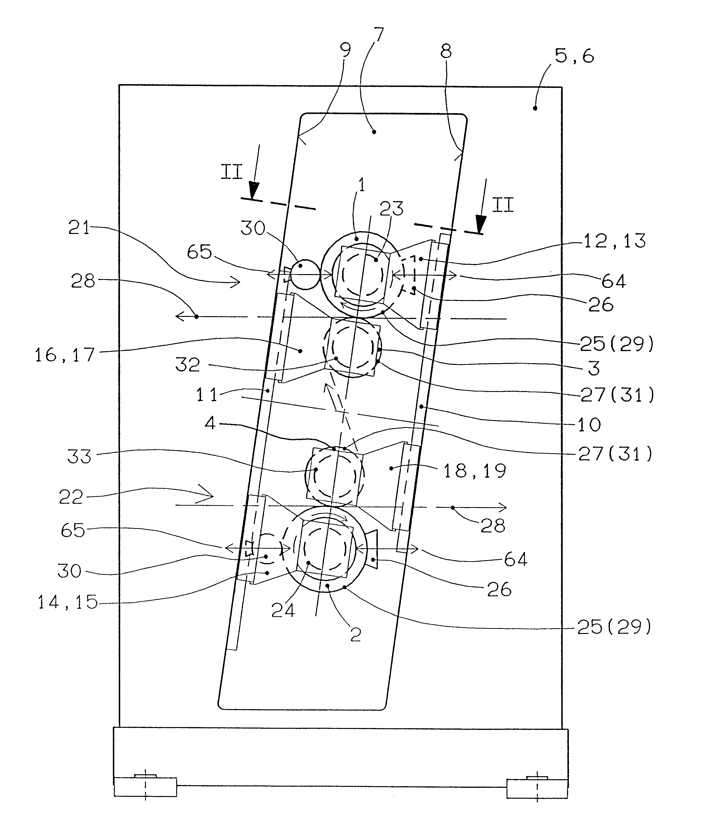
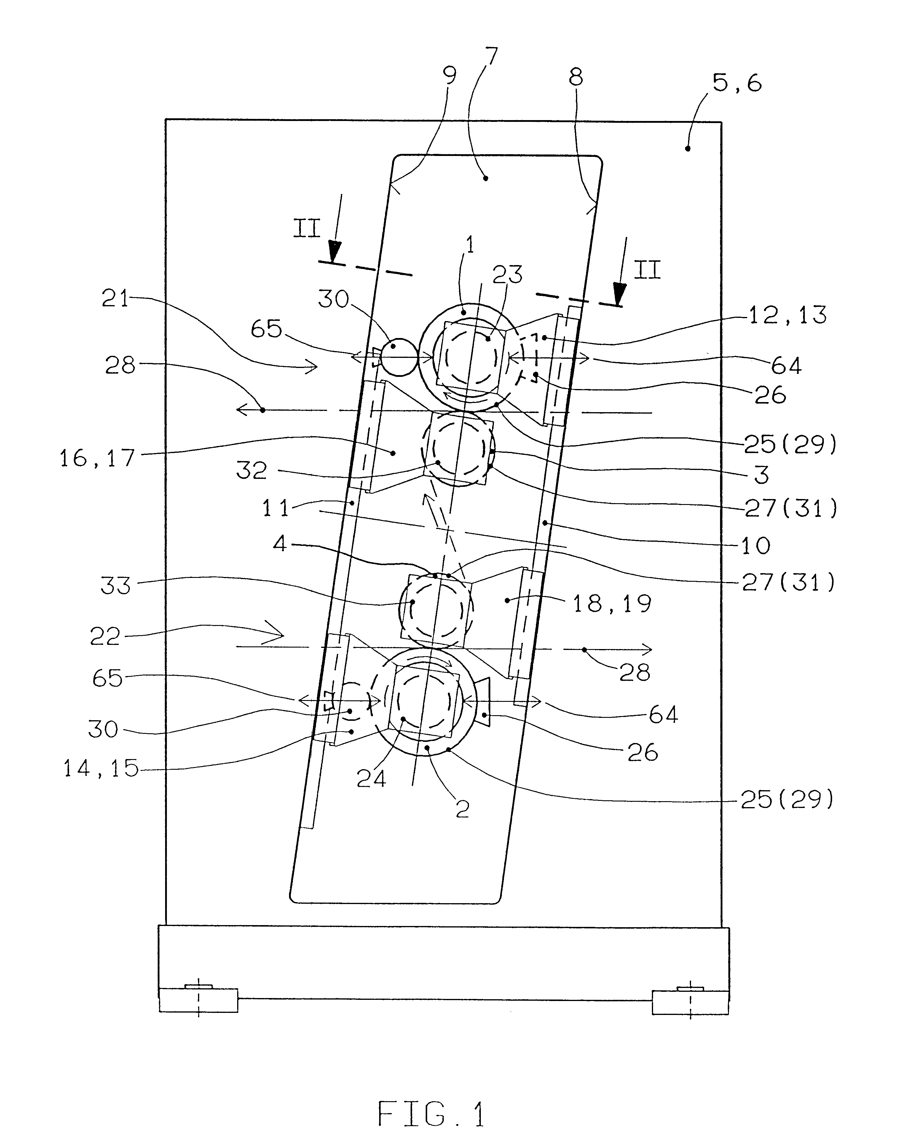
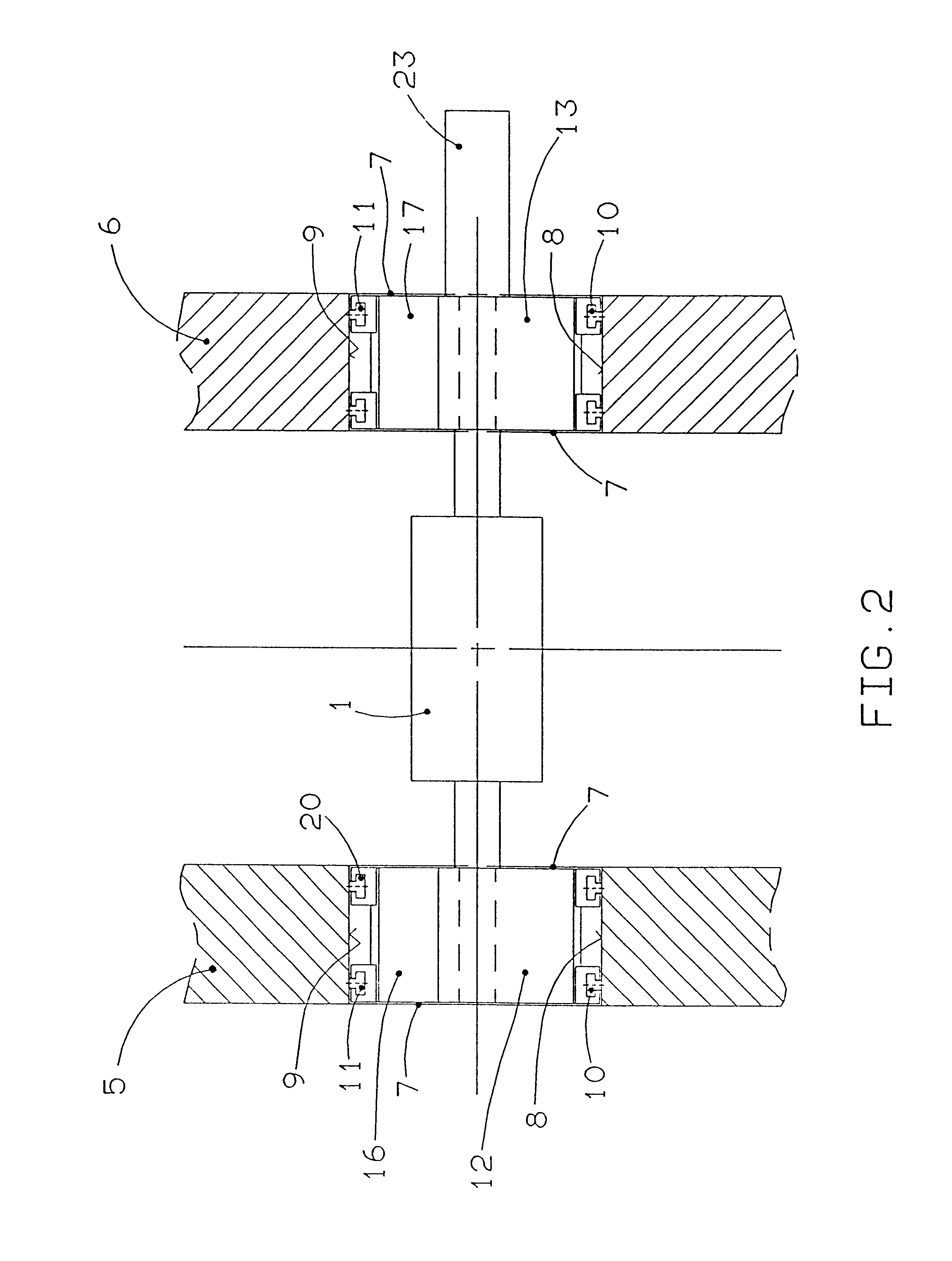
FIG. 1 shows a printing unit of a web-fed rotary printing machine with two forme cylinders 1, 2 and two impression cylinders 3, 4 which are mounted altogether, on each of the two sides, in a side wall 5, 6. Each side wall 5, 6 has an aperture 7 which is delimited by opposite panels 8, 9. The aperture 7 may also be designed, for example, as an open slot. Straight guide elements 10, 11 are arranged on the panels 8, 9.

Each forme cylinder 1, 2 is mounted on each of the two sides, by means of its journal, in a slide 12 to 15. The impression cylinders 3, 4 are likewise mounted on each of their two sides in a slide 16 to 19. The slides 12 to 19 are mounted movably on the guide elements 10, 11 (FIG. 2). In order to provide a form-fitting slide guide, the guide elements 10, 11 have a T-shaped cross section, the crosshead of which engages into a correspondingly designed undercut channel 20 on each slide 12 to 19. For the purpose of movability, each slide 12 to 19 possesses a threaded nut whic...


PUM


Abstract

In order to provide a rotary printing machine for direct printing, in which the printing-assembly cylinders are guided in a stable manner by means of a cost-effective device, the forme cylinder and the impression cylinder of a printing assembly are mounted, adjustably in terms of their mutual spacing, in side walls. At least one of the two cylinders is mounted on both sides in slides movable on straight guide elements which are arranged in each case on at least one of two opposite panels of an aperture in the side walls.

Description

1. Field of the InventionThe invention relates to a web-fed rotary printing machine with at least one printing unit having at least one printing assembly which contains, arranged one above the other, a forme cylinder and an impression cylinder.2. Description of the Related ArtDE 195 34 651 A1 shows a printing assembly for a rotary printing machine for indirect printing. Four printing-assembly cylinders are arranged one above the other, the journal mountings of which are capable of being clamped in jaws which are mounted movably on side walls by means of slides. The cylinders are accessible on the end face through an orifice in the side wall after the jaws have been moved away. The cylinders can then be equipped with sleeves having a different outside diameter. This design involves a relatively complicated construction.According to U.S. Pat. No. 6,085,650 printing-assembly cylinders are mounted in slides which are displaceable on columns. Here, in each case, two cylinders can be posi...

Claims


Application Information

Patent Timeline
Patent Type & Authority Patents(United States)
IPC IPC(8): B41F13/30B41F13/24B41F13/02B41F13/10B41F13/26B41F13/18B41F31/00
CPCB41F13/30B41P2200/12B41P2200/30B41P2213/734
Inventor SCHNEIDER, JOSEFSTAMME, RAINERPETERSEN, GODBER
Owner MANROLANAD AG
Why Eureka
Try Eureka